
lets look at reading from the joystick on the N64

N64_JoystickExample.asm

Platform Specific Series
In this series we'll take a look at hardware related tasks |
Lesson
P1 - Joystick Reading on the N64 lets look at reading from the joystick on the N64 |
|
N64_JoystickExample.asm |
|
Reading the joystick
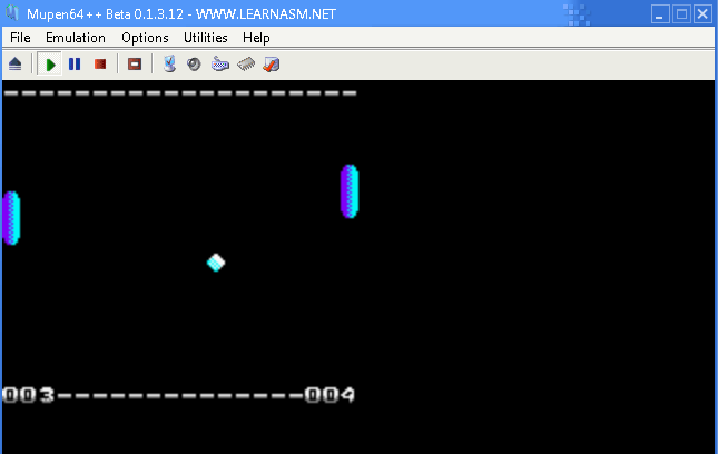
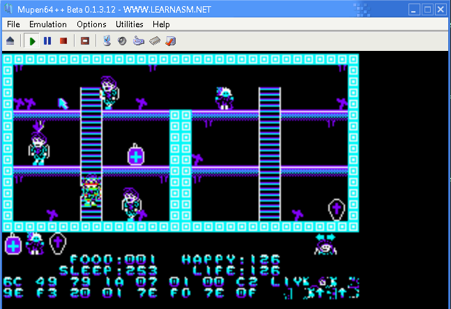
| We're going to read in from the Joystick ports. We'll load in 64 bytes from the serial controller - there are 8 bytes which will be returned from each of the four joysticks. In the screenshot shown UDLR have been pressed on all four controllers Each controller returns the button states and analog data |
 |
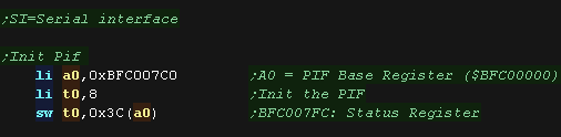
| The N64 controllers are connected via the so called 'PIF' chip
(Peripheral Interface?) The base of the PIF registers is at address 0xBFC007C0 To initialize things we first write 0x8 to the status register at 0xBFC007FC |
 |
| We're going to use the serial interface (SI) to send data to
the PIF, This is basically a DMA copy, which sends a block of data. We need to prepare a 96 byte block of data to send to the PIF to initialize things. We also define 8 bytes to get back the results when we do a read! |
 |
| OK we need to use the SI to Send the INIT code to the PIF The SI registers are at 0xA4800000+ We need to calculate our source address (PIF_Init) - but we need the true 'hardware address' we can get this by ANDing with 0x1FFFFFFF We send the source address to 0xA4800000 (SI_DRAM_ADDR_REG) We want to transfer to the PIF ram at 0xBFC007C0 (PIF_RAM_START) - we also AND this with 0x1FFFFFFF We write the destination to the write register at 0xA4800010 (SI_PIF_ADDR_WR64B_REG) - this write also starts the transfer |
 |
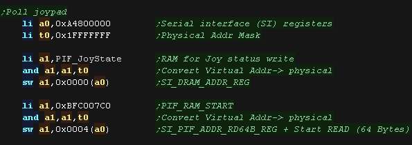
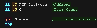
| OK Let's actually get the keypresses from the joypads! This time we use the SI to READ from the PIF. We need to calculate our destination address (PIF_JoyState) - but we need the true 'hardware address' we can get this by ANDing with 0x1FFFFFFF We send the destination address to 0xA4800000 (SI_DRAM_ADDR_REG) - this is the same as the address for writing This time we want to transfer FROM to the PIF ram at 0xBFC007C0 (PIF_RAM_START) - we also AND this with 0x1FFFFFFF We write the source to the read register 0xA4800004 (SI_PIF_ADDR_RD64B_REG) - this write also starts the transfer |
 |
| As a test we dump with our memdump sub There are 8 bytes returned, the first 4 are status, the next 4 are directions and buttons in the format: %ABZSUDLR --LRUDLR XXXXXXXX YYYYYYYY AB - A/B Buttons ZLR - Shoulder buttons / Triggers UDLR - Digital Directions UDLR - C Pad XXXXXXXX YYYYYYYY - Analog stick S - Start |
 |
| The SI makes getting the directions easy! We're defining 'PIF_JoyState' in our ROM, but it's changed during the program, that's because the ROM is actually copied to RAM at execution time by the firmware, so it's actually changeable at run time! |
 |
 |
Lesson
P2 - Joystick Reading on the PSX lets look at reading from the joystick on the Playstation |
|
PSX_JoystickExample.asm |
|
Reading the joystick via the Bios
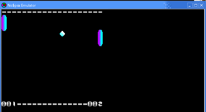
| The easiest way to read in the joypad is via the Bios functions. Here we're pressing the buttons on Joypad 1, and showing the results to the screen. In theory Joypad 2 should be shown as well, but it seems maybe there's an issue with our emulator which stops them working. |
|
|||||||||||||||||||||||||||
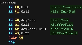
| We're going to execute the bios functions at address 0xB0 (the so
called 'B functions') We need to call this with a function number in T1 - Here we use 0x12 which is 'Init Pad' This takes 4 parameters in A0-A3 A0 is the address of the buffer for joypad 1, A1 is the size (Should be 0x22) A2 is the address of the buffer for joypad 2, A3 is the size (Should be 0x22) |
 |
|||||||||||||||||||||||||||
| Once we have Initialized the joypad we can start the read process. We use Bios function 0x13 'Startpad' - which takes no parameters. This will automatically fill the buffer with the joypad data. |
 |
|||||||||||||||||||||||||||
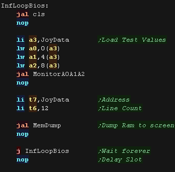
| Here is a crude test program, to read in the raw joypad data and
show it to the screen! The direction buttons have the following bits
|
 |
Reading the joystick Directly!
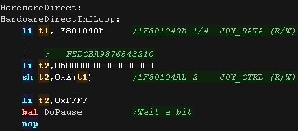
| If we're feeling masochistic we can read from the hardware
directly! We'll need to use various hardware ports to control the hardware. 0x1F801040 JOY_DATA 0x1F801044 JOY_STAT 0x1F801048 JOY_MODE 0x1F80104A JOY_CTRL 0x1F80104E JOY_BAUD |
 |
| We point T1 to the base address of the controller ports. First we reset the control port, via 0x1F80104A We have a small delay to ensure the hardware has time to process the change. |
 |
| Next we set the Baud rate and mode We then select a joystick via the CTRL port. |
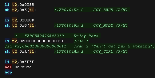 |
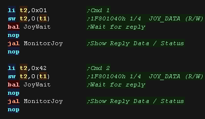
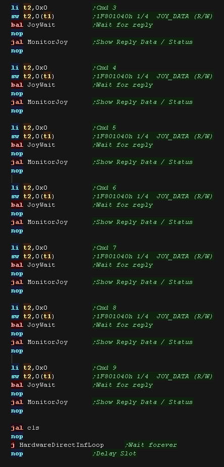
| We send and receive a total of 9 bytes from the joypad We need to send two init bytes to the control port... 0x01 and 0x42 We use JoyWait to wait for a reply, and MonitorJoy to show the returned data and status flags. |
 |
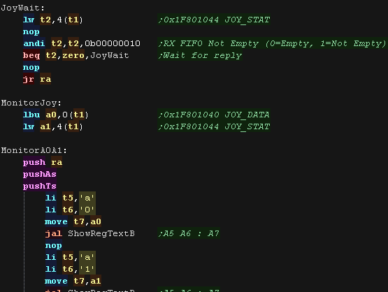
| JoyWait will read in from the status port, and wait for bit 1 to
equal one, this implies a response from the joypad. MonitorJoy is for our testing, it shows the returned data in A0, and status byte in A1 to the screen. |
 |
| We can now read back the data bytes. We repeatedly send a 0x0 byte, and read back the response, this will be a set of digital buttons or an analog axis. |
 |
What Is NativeSprite?
| Nativesprite allows us to use platform specific sprite
capabilities, to form 'objects' (grids of sprites which can be
used in the same way on all systems. This allows us to write a multiplatform program, but gain the benefits of the hardware capabilities. Nativesprite splits the job of drawing sprites into three parts. |
 |
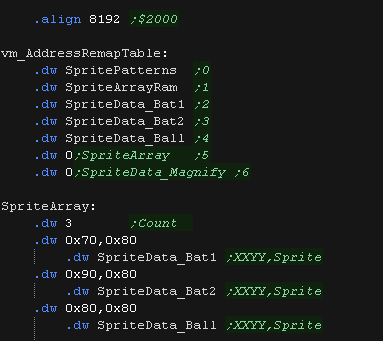
| Part 1 is
multiplatform, it is a list of NativeSprite objects with X,Y
co-ordinates (in logical units - Pairs of Pixels) Our game can change the co-ordinates and sprite object pointers to change in-game graphics in a multiplatform way. With ChibiVM, the 16 bit pointer is a 'numbered entry' in the AddressRemapTable. This is to allow 16 bit ChibiVM to address the 32 bit address space of the MIPS |
 |
| Part 2 is platform
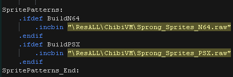
specific, and defines the sprite pattern grid, This defines how the object is made up of hardware sprite patterns. It also offers platform specific functions, like sprite scaling or palettes where available. On systems where no Hardware sprites are available, XOR software sprites are used (made up of 8x8 tiles)... XOR is used because it means we don't need to worry about redrawing the background. On these XOR systems, we define a 16 bit 'pattern number' for each 8x8 pixel 'tile', which is used to calculate an offset within the bitmap pattern data. Part 3 is also platform specific. This is the bitmap pattern data used to draw the sprite, in the format of the hardware sprites or screen memory. |
  |
| We need to define some memory for our variables. nativespriteaddr is the address of the tile pattern bitmap data nativespriteactivebuffer is the settings of the current sprites which have been drawn to the screen, we need this to 'remember' what sprites are there, so we can remove them if they move or change. Because we're using XOR, we just 'redraw' a sprite in it's old position to remove it. On the PSX we cannot access VRAM directly so we must transfer an 8x8 block FROM vram to regular RAM, XOR it and copy it back to VRAM, we use NativeSprite_XORbuffer for this 'temporary store |
 |
| NativeSpr_Init
will prepare the system for drawing sprites. On hardware sprite systems, we transfer patterns to VRAM On the XOR sprite systems we just remember the address we were passed, which contains the bitmap 'tile pattern' data. |
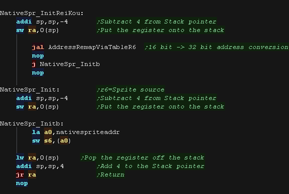 |
| NativeSpr_DrawArray
draws the array of sprite objects defined in Part1 The Co-ordinates of the sprite (in pairs of pixels) and the pointer to the sprite object (part 2) There are two versions: NativeSpr_DrawArrayReiKou is used with ChibiVM, and uses the AddressRemapTable to convert a 16 bit pointer to 32 bits. NativeSpr_DrawArray uses a 32 bit pointer... If you're using NativeSprite on it's own, this is the one you would use. On XOR based systems nativespriteactivebuffer keeps a copy of the positions and sprite objects drawn to the screen, this is used to remove a sprite (VIA XOR - simply redrawing it in the same position) if the position or object changes. We use NativeSpr_DrawOne to draw the sprite to the screen. |
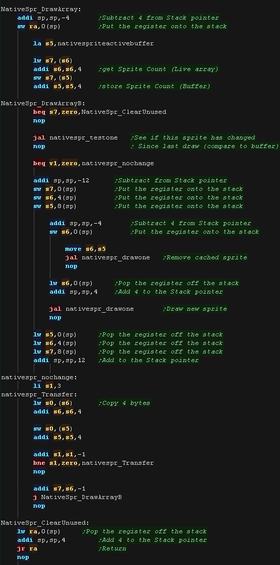 |
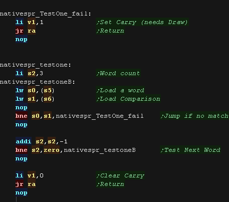
| NativeSpr_TestOne
Checks the 'ActiveBuffer' to see if the XOR sprite is already
drawn to the screen at this position If it is it doesn't need redrawing If it has moved or changed, we remove the old sprite (by XOR drawing it in the same position) then draw the new sprite. |
 |
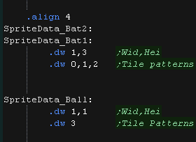
| Here is the correct Object definition
for the XOR systems The Width and Height in patterns is defined in the first two words. On these XOR systems, we define a 32 bit 'pattern number' for each 8x8 pixel 'tile', which is used to calculate an offset within the bitmap pattern data. |
|
| NativeSpr_drawone
will load the parameters of the sprite object to draw loading the
X,Y position into S1,S4,and the object definition address into S5 |
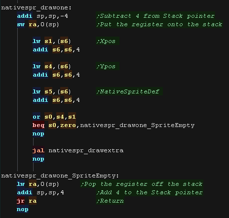 |
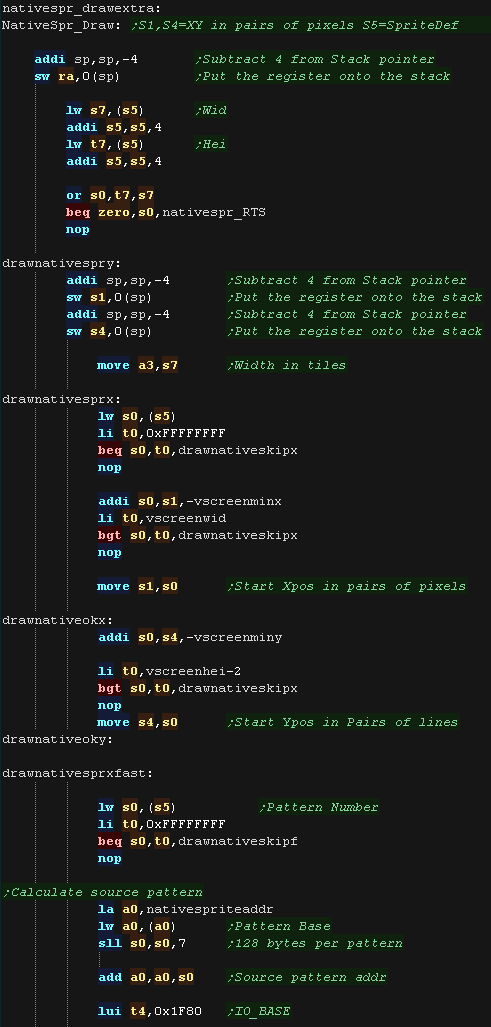
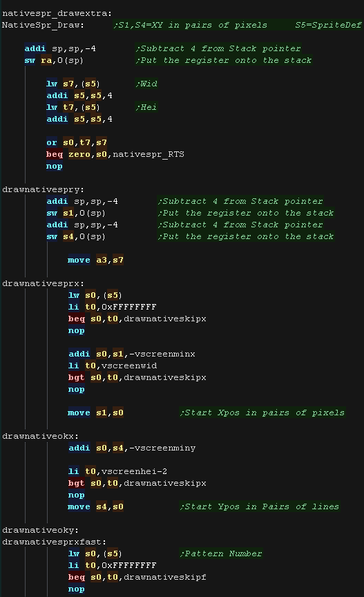
| NativeSpr_DrawExtra
will draw object S5 at position S1,S4 We load in the Width and height of the object (in 8x8 pattern tiles) We load in the pattern number, and see if it's 0xFFFFFFFF (Which is an 'empty pattern' We convert the X,Y co-ordinate from 'Logical units' (pairs of pixels making a centered virtual screen of 128,96 from co-ordinate 64,80) to a screen co-ordinate in pairs of pixels We then calculate the source pattern address for the tile patterns. On these systems each pattern is 128 bytes. |
 |
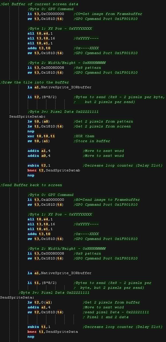
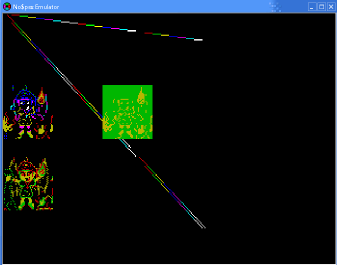
| On the Playstation we can't access VRAM directly. We send commands to 0x1F8001810 to get the video hardware to work for us. We have to use command 0xC0 'Get Image from Framebuffer' to transfer an 8x8 block into RAM (NativeSprite_XORbuffer) We then XOR the source pattern into the buffer. Finally we write it back to screen with command 0xA0 'Send image to Framebuffer' |
 |
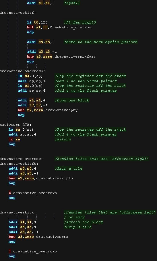
| We repeat for the next tile on the line, and the
other lines that make up this 'spriteobject' drawnative_overrow Handles when part of our spriteobject has gone off the right of the screen. drawnativeskipx Handles when part of the spriteobject is off the left of the screen, or contains empty patterns |
 |
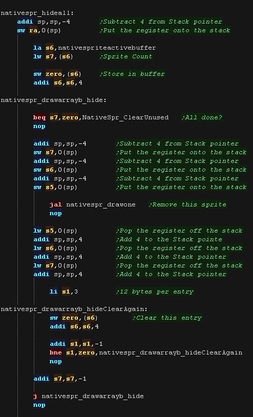
| NativeSpr_HideAll
will remove all the hardware sprites from the screen, and should
be used for things like title screens. It should also be used
before redrawing the background with XOR sprites. With XOR sprites, we walk through the ActiveSpriteBuffer, redrawing each sprite to the screen, which effectively removes it (as we're using XOR) |
 |
What Is NativeSprite?
| Nativesprite allows us to use platform specific sprite
capabilities, to form 'objects' (grids of sprites which can be
used in the same way on all systems. This allows us to write a multiplatform program, but gain the benefits of the hardware capabilities. Nativesprite splits the job of drawing sprites into three parts. |
 |
| Part 1 is
multiplatform, it is a list of NativeSprite objects with X,Y
co-ordinates (in logical units - Pairs of Pixels) Our game can change the co-ordinates and sprite object pointers to change in-game graphics in a multiplatform way. With ChibiVM, the 16 bit pointer is a 'numbered entry' in the AddressRemapTable. This is to allow 16 bit ChibiVM to address the 32 bit address space of the MIPS |
|
| Part 2 is platform
specific, and defines the sprite pattern grid, This defines how the object is made up of hardware sprite patterns. It also offers platform specific functions, like sprite scaling or palettes where available. On systems where no Hardware sprites are available, XOR software sprites are used (made up of 8x8 tiles)... XOR is used because it means we don't need to worry about redrawing the background. On these XOR systems, we define a 16 bit 'pattern number' for each 8x8 pixel 'tile', which is used to calculate an offset within the bitmap pattern data. Part 3 is also platform specific. This is the bitmap pattern data used to draw the sprite, in the format of the hardware sprites or screen memory. |
|
| We need to define some memory for our variables. nativespriteaddr is the address of the tile pattern bitmap data nativespriteactivebuffer is the settings of the current sprites which have been drawn to the screen, we need this to 'remember' what sprites are there, so we can remove them if they move or change. Because we're using XOR, we just 'redraw' a sprite in it's old position to remove it. |
|
| NativeSpr_Init
will prepare the system for drawing sprites. On hardware sprite systems, we transfer patterns to VRAM On the XOR sprite systems we just remember the address we were passed, which contains the bitmap 'tile pattern' data. |
|
| NativeSpr_DrawArray
draws the array of sprite objects defined in Part1 The Co-ordinates of the sprite (in pairs of pixels) and the pointer to the sprite object (part 2) There are two versions: NativeSpr_DrawArrayReiKou is used with ChibiVM, and uses the AddressRemapTable to convert a 16 bit pointer to 32 bits. NativeSpr_DrawArray uses a 32 bit pointer... If you're using NativeSprite on it's own, this is the one you would use. On XOR based systems nativespriteactivebuffer keeps a copy of the positions and sprite objects drawn to the screen, this is used to remove a sprite (VIA XOR - simply redrawing it in the same position) if the position or object changes. We use NativeSpr_DrawOne to draw the sprite to the screen. |
|
| NativeSpr_TestOne
Checks the 'ActiveBuffer' to see if the XOR sprite is already
drawn to the screen at this position If it is it doesn't need redrawing If it has moved or changed, we remove the old sprite (by XOR drawing it in the same position) then draw the new sprite. |
|
| Here is the correct Object definition
for the XOR systems The Width and Height in patterns is defined in the first two words. On these XOR systems, we define a 32 bit 'pattern number' for each 8x8 pixel 'tile', which is used to calculate an offset within the bitmap pattern data. |
|
| NativeSpr_drawone
will load the parameters of the sprite object to draw loading the
X,Y position into S1,S4,and the object definition address into S5 |
|
| NativeSpr_DrawExtra
will draw object S5 at position S1,S4 We load in the Width and height of the object (in 8x8 pattern tiles) We load in the pattern number, and see if it's 0xFFFFFFFF (Which is an 'empty pattern' We convert the X,Y co-ordinate from 'Logical units' (pairs of pixels making a centered virtual screen of 128,96 from co-ordinate 64,80) to a screen co-ordinate in pairs of pixels |
 |
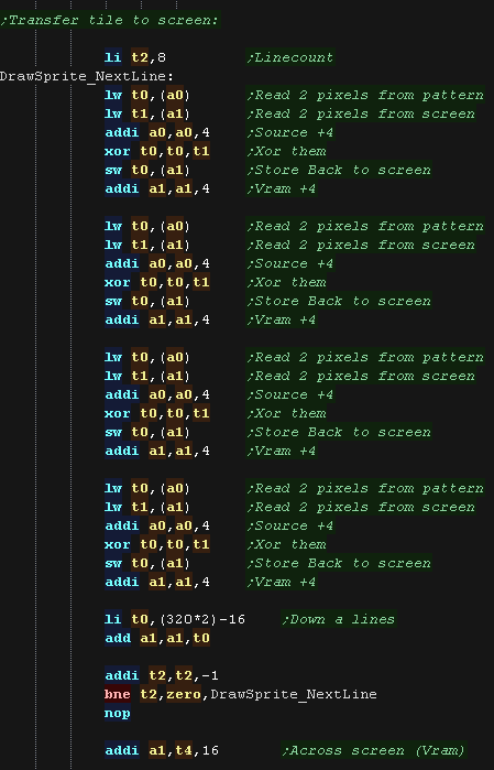
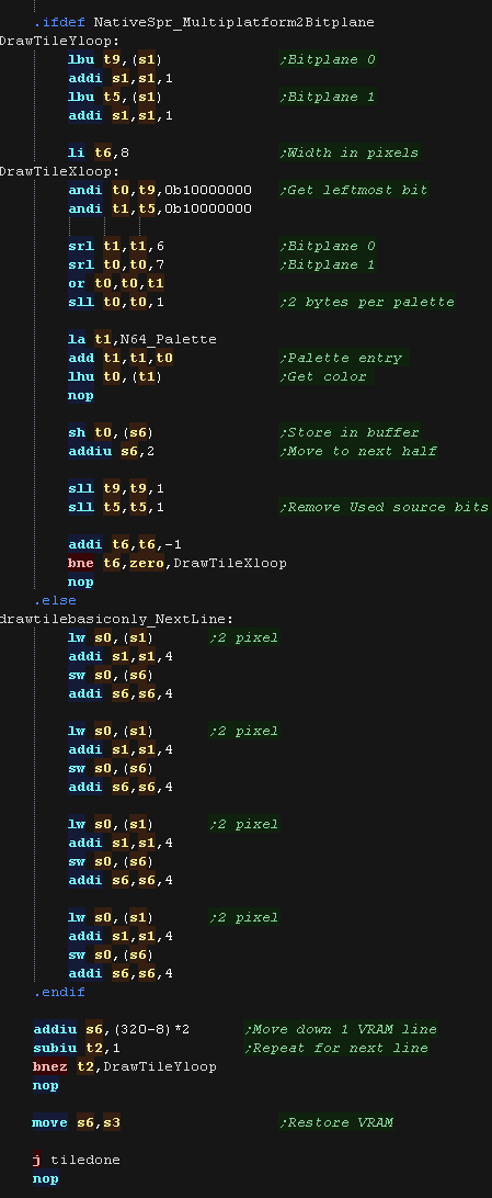
| Next we calculate the VRAM Destination. Each line on the N64 screen is 320 pixels, and each pixel is 2 bytes. We also calculate the source pattern address for the tile patterns. On these systems each pattern is 128 bytes. |
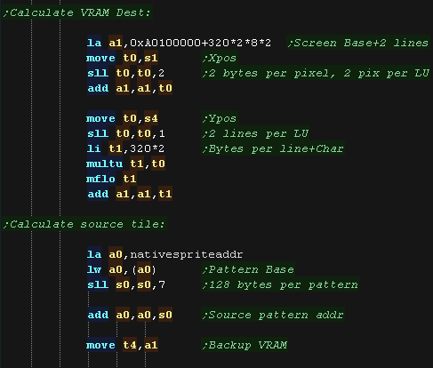 |
| We read 4 bytes (2 pixels) from the source pattern,
xor them with the screen contents, and write back to the screen. We do this 4 times to write a full line, then move down a line (640 bytes - the 16 we just wrote) |
 |
| We repeat for the next tile on the line, and the
other lines that make up this 'spriteobject' drawnative_overrow Handles when part of our spriteobject has gone off the right of the screen. drawnativeskipx Handles when part of the spriteobject is off the left of the screen, or contains empty patterns |
|
| NativeSpr_HideAll
will remove all the hardware sprites from the screen, and should
be used for things like title screens. It should also be used
before redrawing the background with XOR sprites. With XOR sprites, we walk through the ActiveSpriteBuffer, redrawing each sprite to the screen, which effectively removes it (as we're using XOR) |
|
What Is Multiplatform Bitmap?
| Multiplaform bitmap allows us to draw graphics in a common way,
whatever the capabilities of the system! It's intended for low speed drawing or real-time calculated drawing, like drawing title screens, or graphs, or even making a sprite editor or other graphics package! There are 4 functions provided: mpbitmap_setpixel - Set a pixel to a color (0-15) mpbitmap_getpixel - Reads a pixel from the screen mpbitmap_settile - Set an 8x8 pixel tile block (in bitplane format, 1-4 bitplanes) mpbitmap_gettile - Get an 8x8 pixel tile block from the screen (in bitplane format, 1-4 bitplanes) |
 |
Pixel Commands
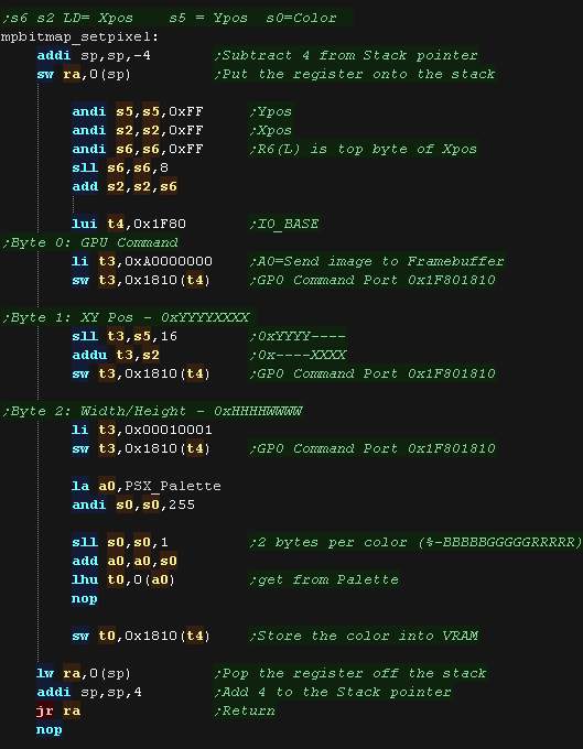
| mpbitmap_setpixel draws a pixel to
the screen The color to set is specified in S0 The Y position in pixels is specified in S5 The Low byte of the X position is specified in S2 The High byte of the X position is specified in S6 (The X position is split into two registers to maintain functional compatibility with the Z80 Version!) To write a pixel to the screen we need to use video command '0xA0' - send image to framebuffer We use the GP0 command port 0x1F801810 to define the command, XY pos, and image size The 'image' in this case is a single 1x1 pixel!!! We convert our numbered pixel (0-15) into the native screen format (%-BBBBBGGGGGRRRRR) We then send it to the screen in the low 16 bits of the word written to the command port |
 |
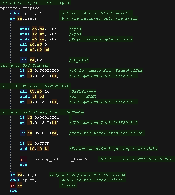
| The mpbitmap_getpixel
function is almost the same, we use command '0xC0' to read back a
byte from the screen. We use mpbitmap_getpixel_FindColor to convert the 16 bits read from the screen (in %-BBBBBGGGGGRRRRR format) into a color number (0-15) ... we do this for compatibility with the other systems (like the Z80 and 6502, were even 16 colors are a luxury!) |
 |
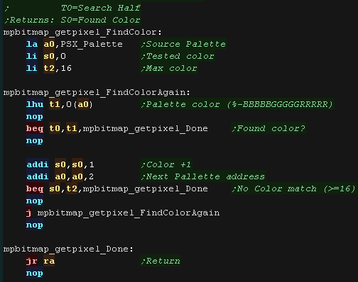
| mpbitmap_getpixel_FindColor will
take a 16 bit value read from the screen, and convert it to a
numbered color using the 'PSX_Palette' We seek entries in the palette, until we find a match, or go through all 16 colors. The 16 color limit is to maintain compatibility with the other systems Multiplatform Bitmap supports. |
 |
Tile Commands
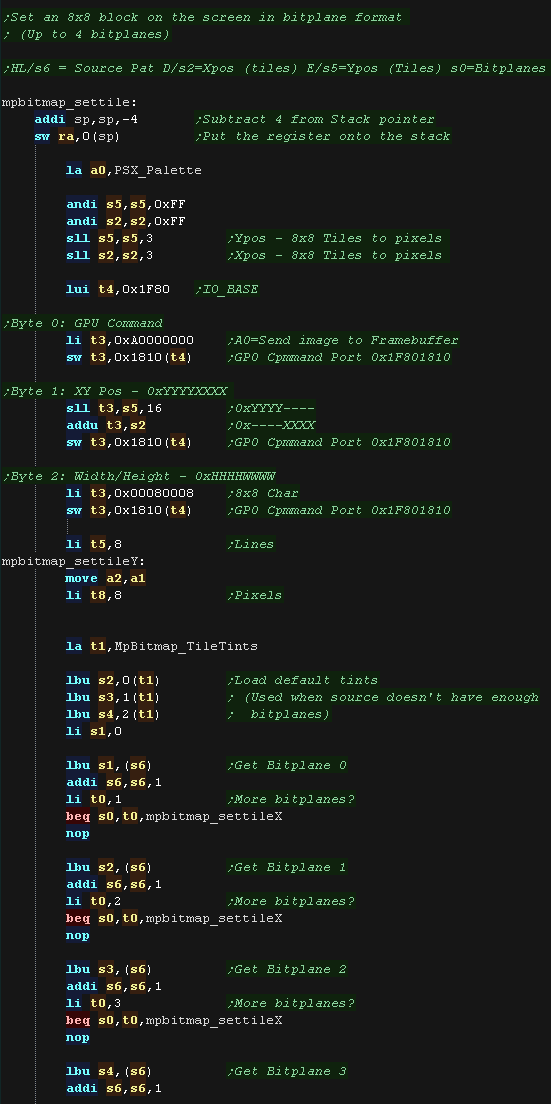
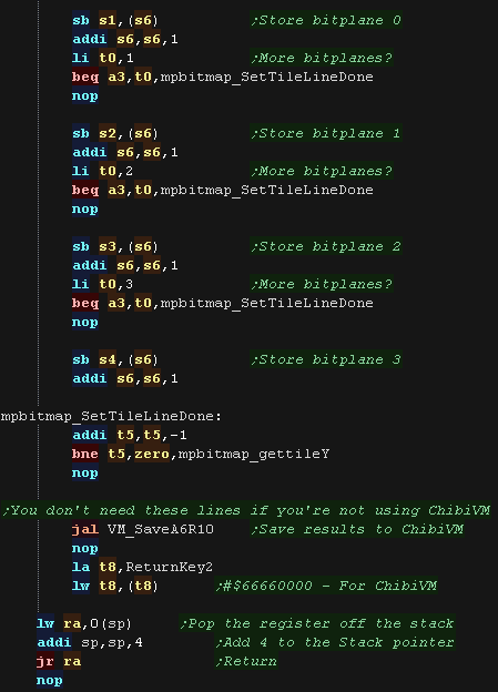
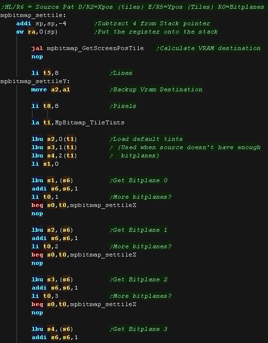
| The 'mpbitmap_settile'
command will take an 8x8 block of data in bitplane format, and draw
it to the screen. Up to 4 bitplanes are supported, meaning 16 colors, 32 bytes for the full tile. We start by selecting the VRAM destination using GPU command 0xA0. Next we load in the bitplanes we've been provided with, The source data may be less than 4 bitpanes, so we load any others from the default 'MpBitmap_TileTints' |
 |
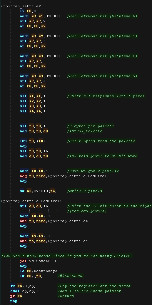
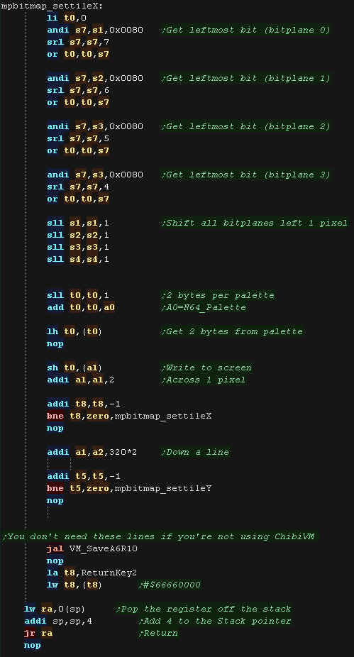
| To calculate the color number we take the most
significant bit from each bitplane byte. We use this as a lookup in our palette, giving us a 16 bit screen-format color. We want to write this to the screen, but we need two pixels of data before we do, so we build them up into a3, until we have a pair, then send them to the screen |
 |
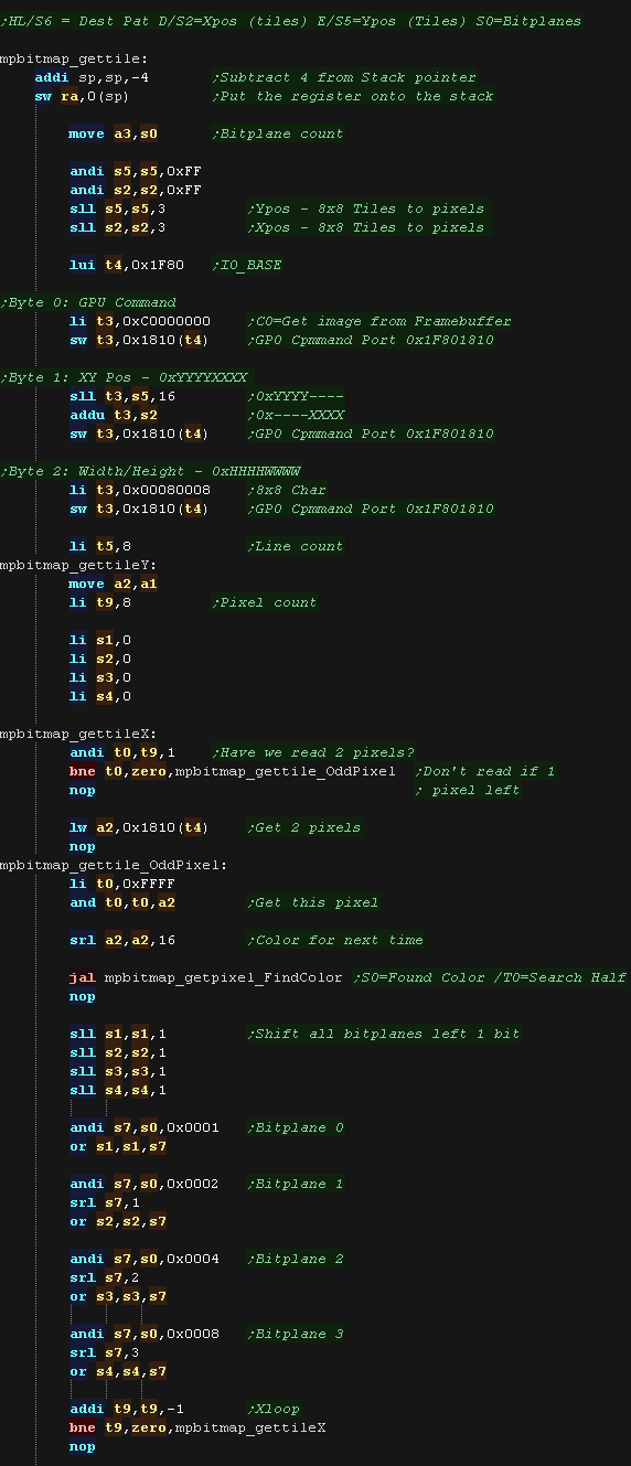
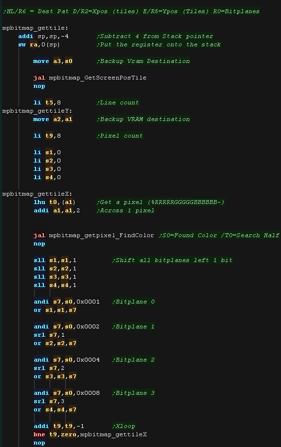
| mpbitmap_gettile will
read pixel data back from the screen, returning 1-4 bitplanes as
required. We read data back from the screen using the 0xC0 command. Each read must load 2 pixels, so we do one read every two pixels. We load in 8 pixels, convert the colors, and shift the bitplane bits into 4 bytes. |
 |
| We store the data back to address S6, writing back as
many bitplanes as we were asked to (originally specified by S0 - now
in A3) |
 |
What Is Multiplatform Bitmap?
| Multiplaform bitmap allows us to draw graphics in a common way,
whatever the capabilities of the system! It's intended for low speed drawing or real-time calculated drawing, like drawing title screens, or graphs, or even making a sprite editor or other graphics package! There are 4 functions provided: mpbitmap_setpixel - Set a pixel to a color (0-15) mpbitmap_getpixel - Reads a pixel from the screen mpbitmap_settile - Set an 8x8 pixel tile block (in bitplane format, 1-4 bitplanes) mpbitmap_gettile - Get an 8x8 pixel tile block from the screen (in bitplane format, 1-4 bitplanes) |
 |
Pixel Commands
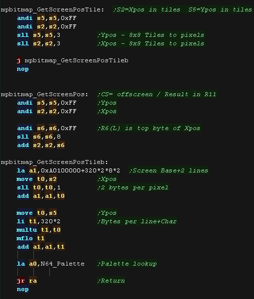
| We need to calculate VRAM destinations. Screen memory starts at 0xA0100000, Each pixel is 2 bytes in the format %RRRRRGGGGGBBBBBB- Each line is 320 pixels. We have two routines to do this mpbitmap_GetScreenPos works in pixels mpbitmap_GetScreenPosTile works in 8x8 tile blocks they also load A0 with the address of the palette (N64_Palette) |
 |
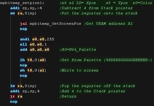
| mpbitmap_setpixel
draws a pixel to the screen The color to set is specified in S0 The Y position in pixels is specified in S5 The Low byte of the X position is specified in S2 The High byte of the X position is specified in S6 (The X position is split into two registers to maintain functional compatibility with the Z80 Version!) We convert our numbered pixel (0-15) into the native screen format %RRRRRGGGGGBBBBBB- using our palette lookup We then write it to the screen. |
 |
| The mpbitmap_getpixel
function works in reverse. We load the pixel from the screen, We then use mpbitmap_getpixel_FindColor to convert the 16 bits read from the screen (in %RRRRRGGGGGBBBBBB- format) into a color number (0-15) ... We do this for compatibility with the other systems (like the Z80 and 6502, were even 16 colors are a luxury!) |
 |
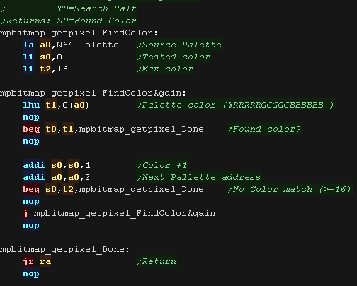
| mpbitmap_getpixel_FindColor
will take a 16 bit value read from the screen, and convert it to a
numbered color using the 'N64_Palette' We seek entries in the palette, until we find a match, or go through all 16 colors. The 16 color limit is to maintain compatibility with the other systems Multiplatform Bitmap supports. |
 |
Tile Commands
| The 'mpbitmap_settile'
command will take an 8x8 block of data in bitplane format, and draw
it to the screen. Up to 4 bitplanes are supported, meaning 16 colors, 32 bytes for the full tile. We start by calculating the VRAM destination. Next we load in the bitplanes we've been provided with, The source data may be less than 4 bitpanes, so we load any others from the default 'MpBitmap_TileTints' |
 |
| To calculate the color number we take the most
significant bit from each bitplane byte. We use this as a lookup in our palette, giving us a 16 bit screen-format color. We write the 16 bit value to the screen (1 pixel). At the end of each line we add 320*2 to the VRAM position, as each line is 320 pixels, and 2 bytes per pixel |
 |
| mpbitmap_gettile will read pixel data back from the
screen, returning 1-4 bitplanes as required. We read data back from the screen, converting it via mpbitmap_getpixel_FindColor We load in 8 pixels, and shift the bitplane bits into 4 bytes. |
 |
| We store the data back to address S6, writing back as
many bitplanes as we were asked to (originally specified by S0 - now
in A3) |
 |
MaxTile Definitions
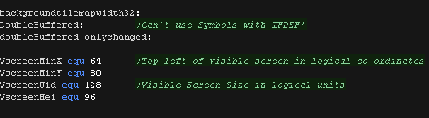
| Maxtile offers X-flip,Y-flip, XY flip, Doubleheight and filled
tiles. It uses software drawing without needing a double buffer. This version supports 'native' 16 bit color tiles (128 bytes per tile - in a format exclusive to the N64) and 'common format' 2 bitplane tiles (16 bytes per tile - in a format which is supported by all systems in my tutorials |
 |
The screen is 256x192, which is 128x96 in logical units. We define the screen size, and memory pointers for the various variables of the test routine. |
 |
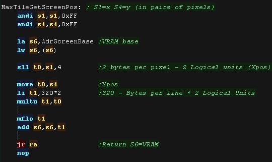
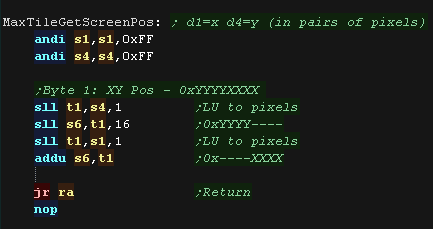
| When we want to draw a sprite object to the screen, we need to calculate the VRAM destination. MaxTile uses X,Y co-ordinates in 'Logical Units' (Pairs of pixels) - this is passed in S1 and S4, and the Vram destination is returned in S6 Each pixel is 2bytes, Each line is 320 bytes. The screen base is defined by AdrScreenBase. |
 |
| The DrawTile Routine is called by the shared code, This shared
code will load the first byte of the 16 bit tile number into R0 The low bit is shifted out (the update bit)... we need to reset it to 0 anyway! The following registers are loaded: S4=Tilemap S5=Tile Bitmap Pattern data S6=VRAM Destination |
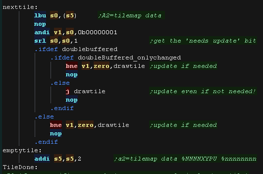 |
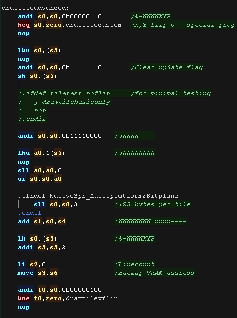
| To optimize things, the tile drawing works as a 'binary tree',
deciding the kind of tile drawing routine to use The Platform specific draw routine DrawTile starts by ckecking Bit 1 (now Bit 0) This is the 'Program' flag - If this is 0, then this is the simplest unflipped tile, otherwise we switch to the advanced routine. If we're drawing a basic tile, we shift a 0 back into S0, and write it back, that clears the Update flag, as we will draw the tile now. |
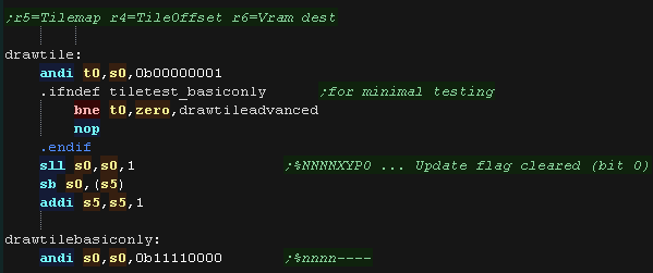 |
| We're going to draw a basic
unflipped tile We need to load the second byte of the tilenumber, and add it to R1 (the pattern data) If we're using true color patterns, we need to bit shift to the left. to multiply by 128 We backup the screenpos into S3, so we can restore it after drawing the tile, and load the line count into T2 We're ready to draw our tile! |
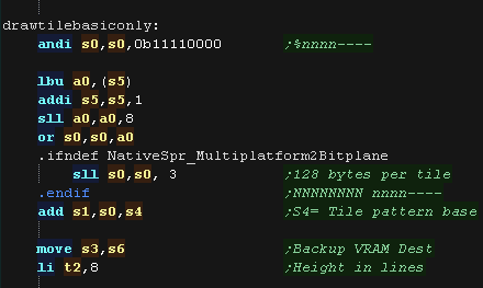 |
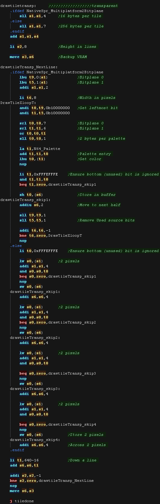
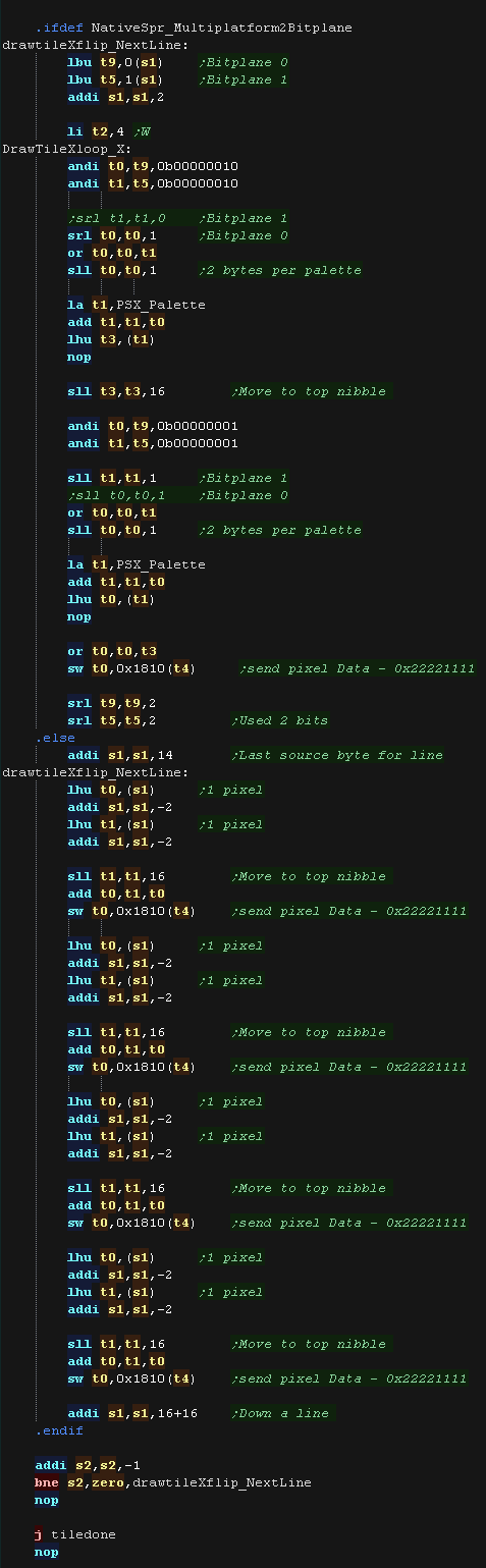
| If we're using 2 bitplane format, we load in a pair
of bytes, this has 'enough bits' for one screen line, so we shift
the bits out into a byte one pixel at a time We need to convert this color 0-3 into a screen 16 bit value, so we do this via a Palette lookup In native format, the source data is in screen format, so we just copy four 32 bit words from the source to the screen. |
 |
| If the Program bit was 1, then either we need to
flip, or run some 'custom code' Next we check the XY bits, if both are 0 this is not a flip (Transparent, Filled, Double etc) If either bit (or both) is 1, then this is some kind of flip, so we calculate the pattern source address, and move it into S1. We also backup the VRAM address into S3 |
 |
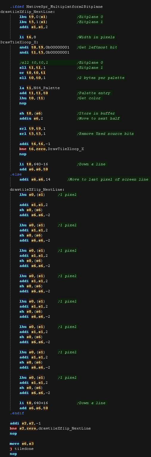
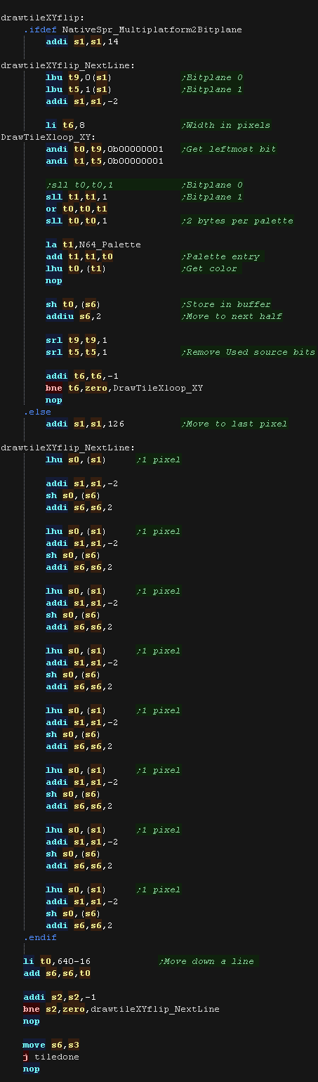
| If the Y flip bit is 0 we must be X flipping! If using 2 bitplane mode, we shift the bits out the Right of the source bytes, and draw them left to right. If using 16 color mode we read Left -> right, but draw right to left. |
 |
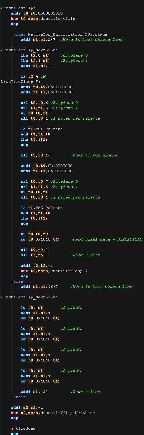
| If the Y flip bit was set we now check if the X
flip bit is also set. If it's not we're just Yflipping! To flip vertically we start from the last line of the source data, and move up after each line is drawn. We draw top to bottom, but read bottom to top! |
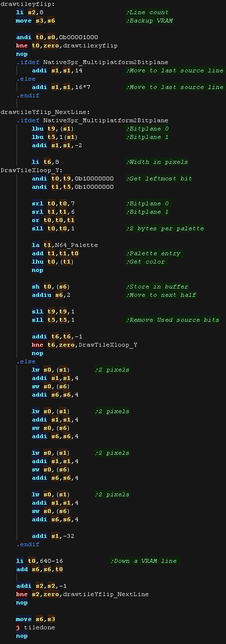 |
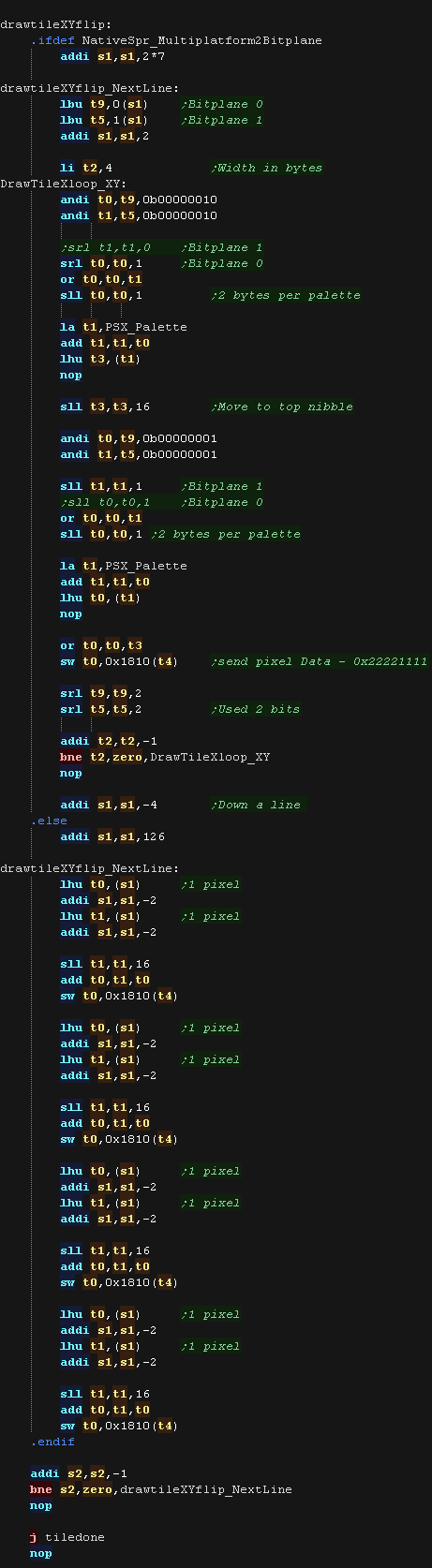
| if the X bit was set as well as Y we need to XY
flip. We do this with a combination of both 'tricks' |
 |
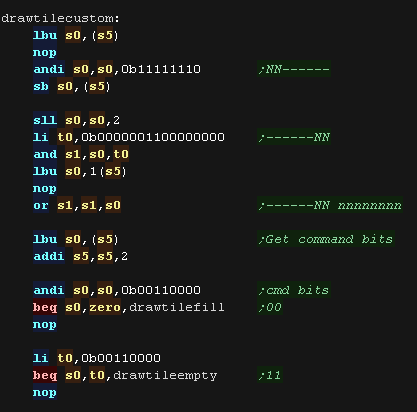
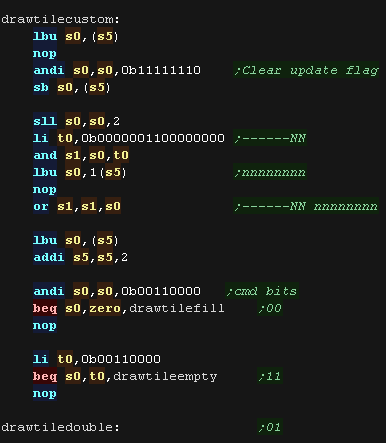
| Bits 1,2,3... XYP=%001 defines a custom program When a custom program is being used Bits 4,5 define the program type (rather than part of the low tile number) %00=Filled Tile %01=Double height tile %10=unused %11=Transparent tile/empty tile The remaining two bits 6,7 act as the High part of the tile number %------NN nnnnnnnn |
 |
| A double height
tile uses only 4 lines of a pattern, We then draw each line of the pattern twice to the screen, We do two lines per loop, repeating 4 times |
 |
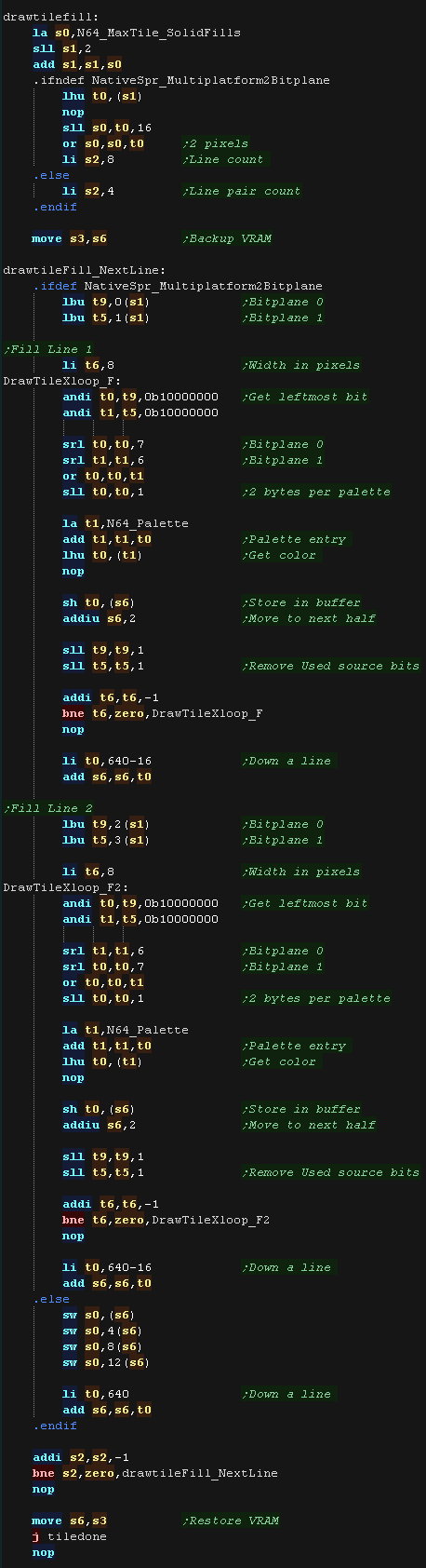
| The fill tile is
the simplest! We load a color from the source data, and draw it to every pixel of the tile. As so little data is read, This routine is the fastest, so should be used for as much as possible of our tilemap! In 2 Bitplane mode, we repeat two lines, this is to allow for 'checkerboard' pattern fills. |
 |
| The final type is the Transparent
tile. if the Tilenumber=255 then this tile is completely transparent, and no data will be drawn |
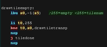 |
| Our transparency is a crude '0 byte' transparency. Basically, any 16 bit word equal to 0 is not drawn to the screen, others are drawn normally. More impressive transparency can be achieved via a LUT and a combination of AND/OR, however this simple transparency is fast, and tends to give a nice 'cartoon' effect with black outlines to characters |
 |
MaxTile Definitions
| Maxtile offers X-flip,Y-flip, XY flip, Doubleheight and filled
tiles. It uses software drawing without needing a double buffer. This version supports 'native' 16 bit color tiles (128 bytes per tile - in a format exclusive to the PSX) and 'common format' 2 bitplane tiles (16 bytes per tile - in a format which is supported by all systems in my tutorials |
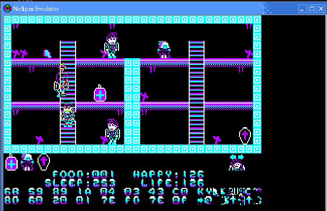 |
The screen is 256x192, which is 128x96 in logical units. We define the screen size, and memory pointers for the various variables of the test routine. |
|
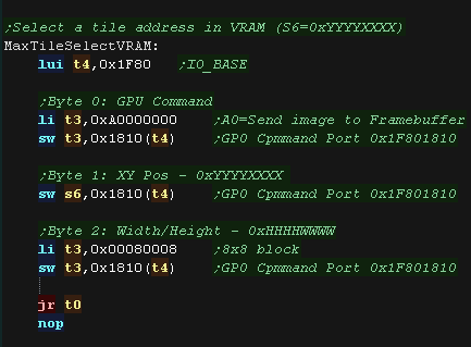
| To draw to the screen we need to send the data to VRAM, but we
can't do this directly We have to define an 'area' that the we're going write, and then send the data the graphics hardware that will fill that area. MaxTileSelectVRAM does this for us |
 |
| When we want to draw a sprite object to the screen, we usually
need to calculate the VRAM destination. MaxTile uses X,Y co-ordinates in 'Logical Units' (Pairs of pixels) - this is passed in S1 and S4, and the Vram destination is returned in S6 To maintain compatibility, the PSX also has a version of this routine, however this time we just combine the X and Y pos in pixels into S6 |
 |
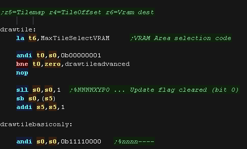
| The DrawTile Routine is called by the shared code, This shared
code will load the first byte of the 16 bit tile number into R0 The low bit is shifted out (the update bit)... we need to reset it to 0 anyway! The following registers are loaded: S4=Tilemap S5=Tile Bitmap Pattern data S6=VRAM Destination |
|
| To optimize things, the tile drawing works as a 'binary tree',
deciding the kind of tile drawing routine to use The Platform specific draw routine DrawTile starts by ckecking Bit 1 (now Bit 0) This is the 'Program' flag - If this is 0, then this is the simplest unflipped tile, otherwise we switch to the advanced routine. If we're drawing a basic tile, we shift a 0 back into S0, and write it back, that clears the Update flag, as we will draw the tile now. Whatever happens, we'll probably need to call MaxTileSelectVRAM, so we load it's address in t6 |
 |
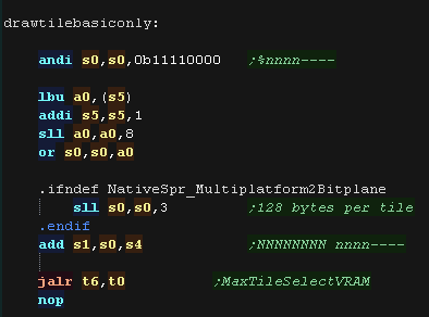
| We're going to draw a basic
unflipped tile We need to load the second byte of the tilenumber, and add it to R1 (the pattern data) If we're using true color patterns, we need to bit shift to the left. to multiply by 128 We're ready to draw our tile! |
 |
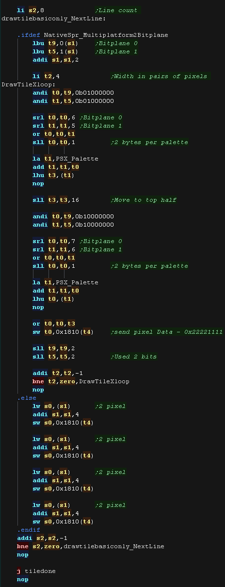
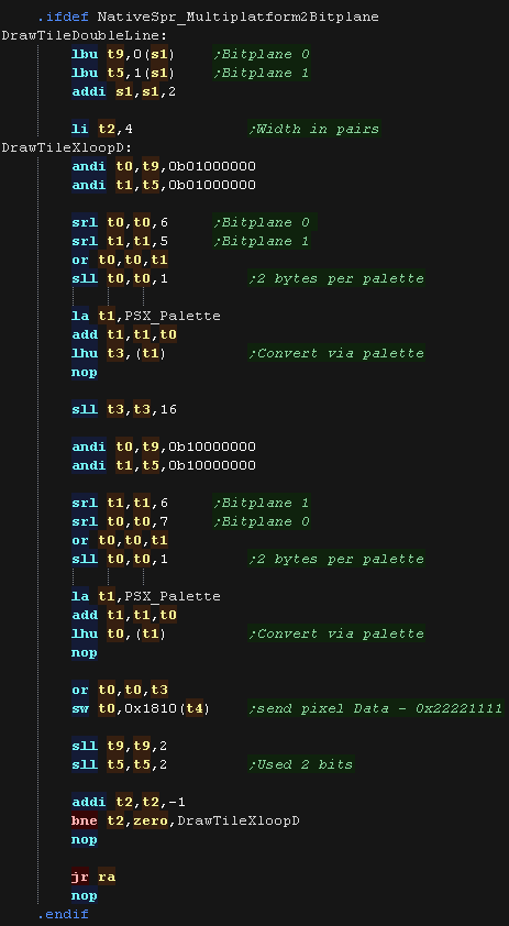
| If we're using 2 bitplane format, we load in a pair
of bytes, this has 'enough bits' for one screen line, so we shift
the bits out into a byte one pixel at a time We need to convert this color 0-3 into a screen 16 bit value, so we do this via a Palette lookup In native format, the source data is in screen format, so we just copy four 32 bit words from the source to the screen. |
 |
| If the Program bit was 1, then either we need to
flip, or run some 'custom code' Next we check the XY bits, if both are 0 this is not a flip (Transparent, Filled, Double etc) If either bit (or both) is 1, then this is some kind of flip, so we calculate the pattern source address, and move it into S1. We also backup the VRAM address into S3 |
 |
| If the Y flip bit is 0 we must be X flipping! If using 2 bitplane mode, we shift the bits out the Right of the source bytes, and draw them left to right. If using 16 color mode we read Left -> right, but draw right to left. |
 |
| If the Y flip bit was set we now check if the X
flip bit is also set. If it's not we're just Yflipping! To flip vertically we start from the last line of the source data, and move up after each line is drawn. We draw top to bottom, but read bottom to top! |
 |
| if the X bit was set as well as Y we need to XY
flip. We do this with a combination of both 'tricks' |
 |
| Bits 1,2,3... XYP=%001 defines a custom program When a custom program is being used Bits 4,5 define the program type (rather than part of the low tile number) %00=Filled Tile %01=Double height tile %10=unused %11=Transparent tile/empty tile The remaining two bits 6,7 act as the High part of the tile number %------NN nnnnnnnn |
 |
| A double height
tile uses only 4 lines of a pattern, We then draw each line of the pattern twice to the screen, We do two lines per loop, repeating 4 times |
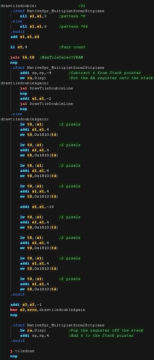  |
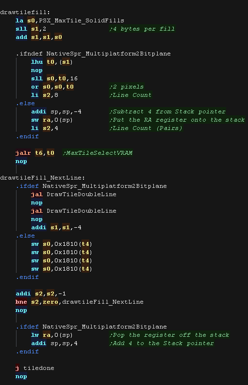
| The fill tile is
the simplest! We load a color from the source data, and draw it to every pixel of the tile. As so little data is read, This routine is the fastest, so should be used for as much as possible of our tilemap! In 2 Bitplane mode, we repeat two lines, this is to allow for 'checkerboard' pattern fills. |
 |
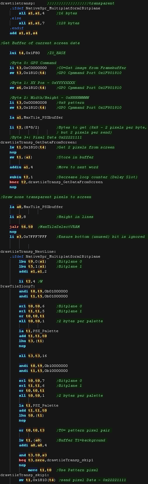
| The final type is the Transparent
tile. if the Tilenumber=255 then this tile is completely transparent, and no data will be drawn |
|
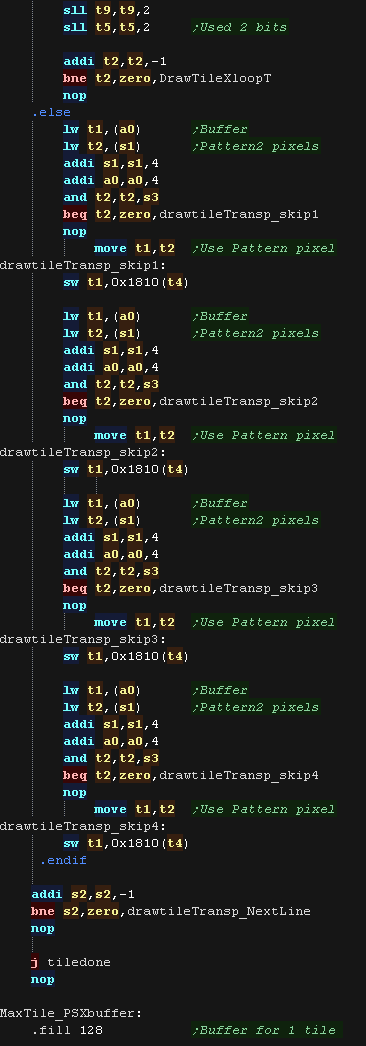
| Our transparency is a crude '0 byte' transparency. Basically, any 16 bit word equal to 0 is not drawn to the screen, others are drawn normally. Because we can't directly access VRAM, we have to read the tile area from the screen into a buffer first (MaxTile_PSXbuffer) We then alter that buffer, and write the changed data back to the screen More impressive transparency can be achieved via a LUT and a combination of AND/OR, however this simple transparency is fast, and tends to give a nice 'cartoon' effect with black outlines to characters |
  |
| Lesson
P9 - MaxTile
Helper Routines Maxtile needs some helper routines which will transfer data to the tilemap, and initialize the tile draw procedure. |
|
V1_MaxTile.asm
|
|
|
Note that these routines are designed to work with ChibiVM. They work 100% the same as they do on the Z80, This means in many cases 16 bit values may be split into two 8 bit parts. This is to ensure multiplatform support |
| A Maxtile tile is
defined by 16 bits in the Little Endian format: %NNNNNNNN NNNNXYPU N=tile Number X=Xflip Y=Yflip P=Program flag (flip + custom tiles) U=Update Flag |
 |
Helper Routines
| Setscroll
sets the X,Y offset for drawing, it can also optionally totally
change the base position of the source tilemap (For moves of many
tiles) The bottom 2 bits of the X,Y offset are used for 'Partial tile shifts' (2 pixel shifts) for relatively smooth scrolling |
 |
| GetTileByteFromHL
Loads a tile number from the address R6 (in the tilemap) 12 of the 16 bits in this are the tile number (4 are for flip and other options), but this routine converts it to a single 8 bit byte. This is intended to allow for easy 'tile comparison' on 8 bit systems, but limits you to up to 256 tiles. |
 |
| maxtileBcLsr
Performs a number of bitshifts on a 16 bit pair in registers R1 (B)
R4 (C) These work with two 8 bit values, as they are used by ChibiVM to bitshift it's 8 bit registers quickly |
 |
| ShifTilemap Returns
the memory address of a tile (16 bit pair) according to the X Y
position in R1,R4 The XY position is measured in TILES (8x8 pixel blocks) |
 |
| ShifTilemapLU Returns
the memory address of a tile (16 bit pair) according to the X Y
position in R1,R4 The XY position is measured in Logical Units (2x2 pixel blocks) Logical units are also used by NativeSprite, so allow for easy comparison between a sprite position, and the underlying tile map. |
 |
| MaxTileFlagForRedraw Flags part of
the tilemap for redrawing (Setting Bit 0 of the little endian 16 bit
tile pairs) This ensures the flagged tiles are redrawn when the tilemap is next 'drawn' |
 |
| MaxTilePrint Works
like a 'PrintString' routine. A 2 dimentional sequence of one byte 'tiles' is 'printed' to the tilemap, each line is 255 terminated, and the whole sequence s 255 terminated. While the left side of the area will be aligned, the lines can be different lengths, it's intended for printing a 'paragraph' of text to the tilemap. Although each tile can only be defined by a value of 0-254, an 'offset' is added to this number before writing to the tilemap, allowing for options like X/Y flip to even be used. |
 |
| MaxTileDrawArea Draws
a square grid of tiles from a source tilemap to the main tilemap Unlike 'Print' routines, this uses full 16 bit tiles and always works in a square area. |
 |
| MaxTilePrintArea Draws
a square grid of tiles from a source tilemap to the main tilemap Unlike 'MaxTileDrawArea' routines, this uses 8 bit source tiles, with a 16 bit offset (like MaxTilePrint) This is intended to save memory by halving the size of the source tilemap. Note This version loads some of it's parameters directly from ChibiVM registers R8-R11 (Zeropage 16+) |
  |
| MaxTileFillArea Fills an area of the tilemap with a single 16 bit tile. |  |
Draw Routine
| MaxTileRedraw will redraw any changed tiles to the
screen (Based on the Update Flag. First we load in the address of the Tilemap, and the bitmap pattern data. We also load in the width of the tilemap in bytes (usually 36x2) We check the 'partial tile shift' - Our draw routines can only draw whole tiles, so if we need to shift, we do this by adding to the draw position. This means the edges of the screen may not be properly drawn, but the solution to this is to draw a 'border' covering 6 pixels of the edges of the screen, which hides these incomplete tiles. |
 |
| The Draw routine moves through the tilemap, checking
bit 0 of each tile (The Update Flag) and running drawtile if the bit
was set We process each line of the tilemap, then move down to the next line (in the tilemap, and of course also the screen) and repeat |
 |