
Platform Specific Lessons
 |
Lesson
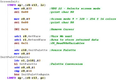
P1 - Bitmap graphics and Palette definitions on Risc OS Lets start with RISC-OS... we'll learn how to enable graphics mode, and draw bitmap graphics to the screen. Let's make a start! |
 |
 |
 |
 |
There
are a wide range of screen modes available, but we'll only be
using 9!... the 256 color mode is a little weird as it uses 64
base colors with different brightnesses, so you'll probably find
this 16 color mode easier. If you want all the details take a look here! |
| Want to create a valid file? you can use my AkuSprite Editor, it's free and open source, and included in the sources file. | 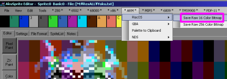 |
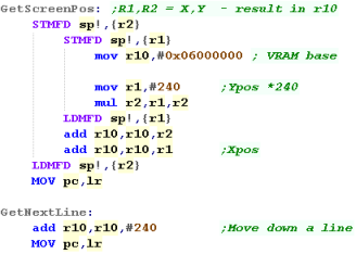
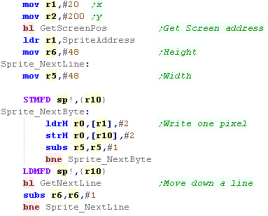
| OK, First we need to set up our screen... we're going to use
'Screen mode 3'... this gives a 16pp bitmap screen (2 bytes per
pixel) at ram address 0x06000000 This screen mode only works on Background Layer 2 To turn it on we need to set graphics register x04000000 - bits 0-2 are the Screen mode, bit 10 turns on Background 2 Once the screen is on, we'll fill the screen! The screen starts at 0x06000000 and has 256x192 pixels... where each pixel takes 2 bytes in the format 'ABBBBBGGGGGRRRRR'... with 1 Alpha bit and 5 Blue, Green and Red bits |
 |
 |
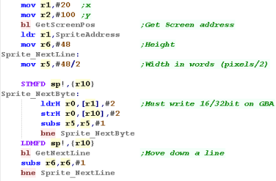
This screen
mode uses 2 bytes (a Half-Word) per pixel... but whatever screen
mode you use, you need to make sure you write to the screen in
WORDS - Writing individual bytes to the screen - even in 256
color mode will not work! |
| Want to create a valid file? you can use my AkuSprite Editor, it's free and open source, and included in the sources file. |  |
| Even though 1
pixel takes a single byte we have to write in WORDS -
otherwise both pixels will be set at the same time! You'll have to program accordingly to work around this limitation! |
 |
| Want to create a valid file? you can use my AkuSprite Editor, it's free and open source, and included in the sources file. |  |
Enabling graphics hardware
| The NDS has two graphics engines - Engine A is the most powerful
and can do 3D - Engine B is around the same spec as a GBA Each Engine can only drive one screen - so we need both for dual screens (That's why most games have simple graphics on one screen) Before we can use either, we need to turn them on with reg 0x4000304 |
 |
| We'll allocate Engine A to the top screen, and
Engine B to the bottom Though A is more powerful, we're only doing simple graphics so it won't make much difference. |
 |
| Engine A can map an area of normal memory straight onto the
screen as a 16 bit 256x192 image (VRAM Display) We do this by setting bits 16 and 17 of 0x4000240 to 'Mode 2' |
 |
| The last command enabled the screen, but we must also turn on
it's ram... We do this with 0x4000240 Now Words written to 0x06800000+ will set pixels of the top screen in format -BBBBBGGGGGRRRRR |
 |
 |
If you only want one screen - we're done! If you want two, it's tricky... Engine B can't do RAM displays as easily, but we can do it in a more tricky way!... read on! |
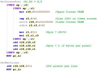
We can write to both our screens in almost the same way - the
only difference is the bottom screen uses Alpha in bit 15
(1=Visible)... the top screen doesn't use it
|
 |
|||||||||
| What a lot of effort! The screen is finally, on, clear and ready for us to draw some data! |
 |
| Want to create a valid file? you can use my AkuSprite Editor, it's free and open source, and included in the sources file. |  |
 |
Key reading on Risc OS |
The RiscOS keycodes can be seen below:
| Esc:112 | F1: 113 | F2: 114 | F3: 115 | F4: 20 | F5: 116 | F6: 117 | F7: 22 | F8: 118 | F9: 119 | F10:30 | F11: 28 | F12: 29 | Print: 32 | ScrlLk:31 | Brk:44 | ||||||||
| `: 45 | 1: 48 | 2: 49 | 3: 17 | 4: 18 | 5: 19 | 6: 24 | 7: 36 | 8: 21 | 9: 38 | 0: 39 | -: 23 | =: 93 | Pnd: 46 | Bksp: 47 | Ins: 61 | Home:62 | PgUp:63 | NmLk: 77 | /: 74 | *: 91 | #: 90 | ||
| Tab: 96 | Q: 16 | W: 33 | E: 34 | R: 51 | T: 35 | Y: 68 | U: 53 | I: 37 | O: 54 | P: 55 | [: 56 | ]: 88 | \: 120 | Del: 89 | Copy:105 | PgDown:78 | 7: 27 | 8: 42 | 9: 43 | -: 59 | |||
| Ctrl: 14 | A: 65 | S: 81 | D: 50 | F: 67 | G: 83 | H: 84 | J: 69 | K: 70 | L: 86 | ;: 72 | ': 79 | Retn: 73 | 4: 122 | 5: 123 | 6: 26 | +: 58 | |||||||
| Shift: 03 | Z: 97 | X: 66 | C: 82 | V: 99 | B: 100 | N: 85 | M: 101 | ,: 102 | .: 103 | /: 104 | Shift:06 | U:57 | 1: 107 | 2: 124 | 3:108 | Enter: 60 | |||||||
| Caps: 64 | Alt: 25 | Spc: 98 | Alt:28 | Ctrl: 17 | L:25 | D:41 | R:121 | 0:106 | .:76 |
 |
Joypad Reading on the Gameboy Advance |
| Reading in the GBA buttons is super easy!... just read in from
0x4000130... you'll get a word back with all the keys in the
format %------LRDULRSsBA Um... that's it! |
 |
| A bit is 1 if the key isn't pressed.. 0 if the key is pressed Here we pressed Down and A |
 |
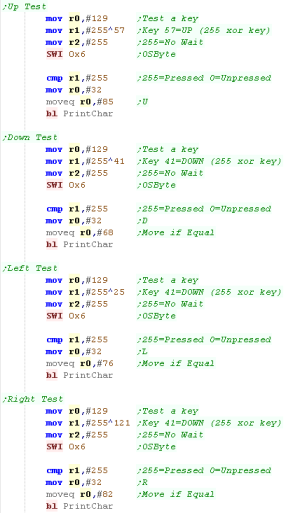
| The 'GBA' key reading we see here is the same
on the NDS... Which is nice and easy! Unfortunately, reading the other keys is not!... for some reason the NDS only keys are a right pain! |
 |
 |
Joypad Reading on the Nintendo DS |
 |
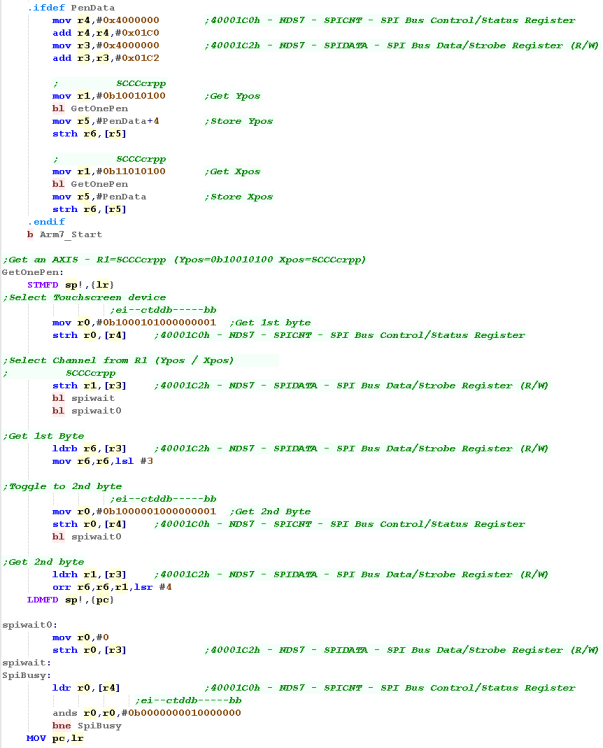
PEN Reading on the Nintendo DS |
 |
Lesson
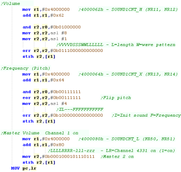
P6 - Sound on the Gameboy Advance The GBA retains the same basic functions of the Gameboy Color... Here we'll learn how to make simple sounds for our games. |
 |
 |
 |
Introducing ChibiSound!
| In these tutorials we're going to
create an 'amazing' new sound API to rival Directsound!!!... well at
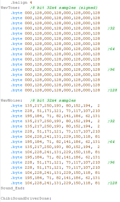
least the functionality won't break like Directsound 3D did! Well, no it won't... what it will do is take a byte value from 0-255, and make a sound of selectable pitch, with noise or half volume in a similar way on all our systems! This was created for Grime Z80, and allows common sound code to give similar effects on all the systems! All we do is load the accumulator with a value, and call ChibiSound! Of course, this won't be enough to make musicbut it will give us some simple SFX, and make it easy to compare doing simple tasks on our various systems! |
|
Sound Ports
| Port | Name | Description | Bits | Details |
| 4000060h | SOUND1CNT_L | Channel 1 Sweep register | ---------TTTDSSS | S=sweep shift D=direction T=Time |
| 4000062h | SOUND1CNT_H | Channel 1 Duty/Length/Envelope (NR11 | VVVVDSSSWWLLLLLL | L=length W=wave pattern duty S=envelope Step D= env direction V=Volume |
| 4000064h | SOUND1CNT_X | Channel 1 Frequency/Control | IL---FFFFFFFFFFF | I=Init sound L=no loop F=Frequency |
| 4000068h | SOUND2CNT_L | Channel 2 Duty/Length/Envelope (NR21 | VVVVDSSSWWLLLLLL | L=length W=wave pattern duty S=envelope Step D= env direction V=Volume |
| 400006Ch | SOUND2CNT_H | Channel 2 Frequency/Control | IL---FFFFFFFFFFF | I=Init sound L=no loop F=Frequency |
| 4000070h | SOUND3CNT_L | Channel 3 Stop/Wave RAM select (NR30) | -------PBD----- | D=Dimension B=Bank P=Play |
| 4000072h | SOUND3CNT_H | Channel 3 Length/Volume | FVV-----LLLLLLLL | L=sound Length V=volume F=Force |
| 4000074h | SOUND3CNT_X | Channel 3 Frequency/Control | IL---FFFFFFFFFFF | I=Init sound L=no loop F=Frequency |
| 4000078h | SOUND4CNT_L | Channel 4 Length/Envelope | VVVVDSSS--LLLLLL | L=length S=envelope Step D= env direction V=Volume |
| 400007Ch | SOUND4CNT_H | Channel 4 Noise Frequency/Control | IL------SSSSCRRR | R=dividing Ration, C=Counter S=shify clock freq L+no Loop I=Init sound |
| 4000080h | SOUNDCNT_L | Control Stereo/Volume/Enable | LLLLRRRR-lll-rrr | LR=Channel on lr=master vol(7=max) |
| 4000082h | SOUNDCNT_H | Control Mixing/DMA Control | BBBBAAAA-ba-VV | |
| 4000084h | SOUNDCNT_X | Control Sound on/off | M---4321 | M=Master ON 1234 (Read) = Sound on flag |
| 4000088h | BIOS SOUNDBIAS | Sound PWM Control | AA----BBBBBBBBB- | A=Amplitude B=Bios |
| 4000090h | WAVE_RAM | 16 Bytes | 1111222233334444 | 4 bit sample data |
| 40000A0h | FIFO_A | Channel A FIFO | ----DDDD----DDDD | D=Wawave Data |
| 40000A4h | FIFO_B | Channel B FIFO | ----DDDD----DDDD | D=Wawave Data |
Writing ChibiSound
| Of course, the GBA can
do more than just simple beeps, it's capable of playing digital
sound samples. But for now we'll make do with some basic beeps. |
 |
Introducing ChibiSound!
| In these tutorials we're going to
create an 'amazing' new sound API to rival Directsound!!!... well at
least the functionality won't break like Directsound 3D did! Well, no it won't... what it will do is take a byte value from 0-255, and make a sound of selectable pitch, with noise or half volume in a similar way on all our systems! This was created for Grime Z80, and allows common sound code to give similar effects on all the systems! All we do is load the accumulator with a value, and call ChibiSound! Of course, this won't be enough to make music but it will give us some simple SFX, and make it easy to compare doing simple tasks on our various systems! |
|
Sound Registers (ARM7)
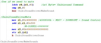
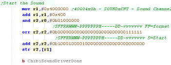
Like pen control, the main ARM9 CPU cannot access the sound hardware... so we'll program a routine on the ARM7 and use a couple of bytes of shared ram to pass commands to the Arm7 routine
There are 16 sound channels, with addresses like 40004x0h where x is a channel from 0-F
| Address | Bytes | Name | Description | Bits | Notes |
| 4000304h | 2 | POWCNT2 | Sound/Wifi Power Control Register (R/W) | ------WS | S=Sound on W=Wifi on |
| 40004x0h | 4 | SOUNDxCNT | Sound Channel X Control Register (R/W) | SFFRRWWW-PPPPPPPH-----DD-VVVVVVV | S=Start F=Format R=Repeat W=Wave duty P=Panning H=Hold D=volume Div V=Volume |
| 40004x4h | 4 | SOUNDxSAD | Sound Channel X Data Source Register (W) | -----AAAAAAAAAAAAAAAAAAAAAAAA00 | A=Address of sample |
| 40004x8h | 2 | SOUNDxTMR | Sound Channel X Timer Register (W) | FFFFFFFFFFFFFFFF | F=Frequency |
| 40004xAh | 2 | SOUNDxPNT | Sound Channel X Loopstart Register (W) | LLLLLLLLLLLLLLLL | L=Loop Start |
| 40004xCh | 4 | SOUNDxLEN | Sound Channel X Length Register (W) | LLLLLLLLLLLLLLLL | L=Length |
| 4000500h | 2 | SOUNDCNT | Sound Control Register (R/W) | M-31RRLL-VVVVVVV | M=Master on 31=output 31 to mixer RRLL=output from V=master Volume |
| 4000504h | 2 | SOUNDBIAS | Sound Bias Register (R/W) | -------BBBBBBBBBB | B=Sound Bias |
| 4000508h | 1 | SNDCAP0CNT | Sound Capture 0 Control Register (R/W) | S---FEsC | S=Start F=Format R=Repeat s=source C=Control |
| 4000509h | 1 | SNDCAP1CNT | Sound Capture 1 Control Register (R/W) | S---FEsC | |
| 4000510h | 4 | SNDCAP0DAD | Sound Capture 0 Destination Address (R/W) | -----AAAAAAAAAAAAAAAAAAAAAAAA00 | A=Address of Capture |
| 4000514h | 2 | SNDCAP0LEN | Sound Capture 0 Length (W) | LLLLLLLLLLLLLLLL | L=Length |
| 4000518h | 4 | SNDCAP1DAD | Sound Capture 1 Destination Address (R/W) | -----AAAAAAAAAAAAAAAAAAAAAAAA00 | |
| 400051Ch | 2 | SNDCAP1LEN | Sound Capture 1 Length (W) | LLLLLLLLLLLLLLLL | L=Length |
Writing ChibiSound
The ChibiSound Driver on the ARM7
 |
Remember... these commands only work from
the ARM7 - you need to define a separate program for that CPU to
run in the header... Don't know how to do that? No problem! check out the files in the sources download! What? You can't be bothered? Sheesh! Well I guess you didn't really want to know then! |
Setting up the tilemap
 |
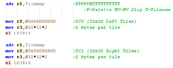
The
64x32 tilemap is actually made up of 2x 32x32 tilemaps! The Left hand half of the tilemap is at 06000000h The Right hand half of the tilemap is at 06000800h |
Setting up the tilemap
| The
DS version is almost the same, we just need to do a bit more
initialization to get the system set up. |
 |
Using the Tilemap on the Nintendo DS
1D Sprites and 2D Sprites
| Sprite data for sprites larger than 8x8 can be organized on one of
two formats. In 1D mode, Sprite patterns are organized in a linear format (this is the format this example uses) If we were to show a crosshair from sprite data it would use tiles 1,2,3,4 In 2D mode, Sprite patterns are organized according to a 32,32 grid. If we were to show a crosshair from sprite data it would use tiles 1,2,33,34 |
1D Mode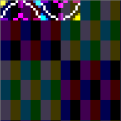 |
2D Mode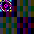 |
Enabling Hardware Sprites
 |
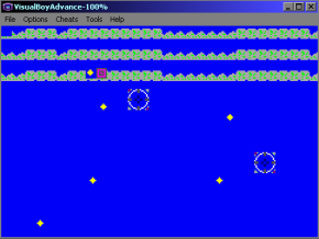
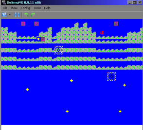
We're going to create some
simple (unrotated) sprites, The GBA and NDS are capable of
more, but it's tricky, and it's outside of the scope of what
we'll try to do here. |
Enabling Hardware Sprites
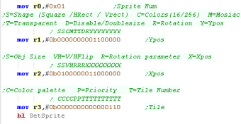
Hardware sprites are defined by 3 words... there are 128 in total.
Sprites are defined with 6 bytes from 7000000h Onwards... there are two
bytes after each sprite definition which are used by rotation settings
Sprite 0 is defined by 7000000h+,Sprite 1 is defined by 7000008h+,Sprite 1 is defined by 7000010h+ and so on.
| H Byte | L Byte | ||||||||||||||||
| Vram Address | F
|
E
|
D
|
C
|
B
|
A
|
9
|
8
|
7
|
6
|
5
|
4
|
3
|
2
|
1
|
0
|
|
| 7000000h | S | S | C | M | T | T | D | R | Y | Y | Y | Y | Y | Y | Y | Y | Y=Ypos S=Shape
(Square, HRect, Vrect) C=Colors(16/256)
M=Mosiac T=Transparent D=Disable/Doublesize R=Rotation |
| 7000002h | S | S | V | H | R | R | R | X | X | X | X | X | X | X | X | X | X=Xpos S=Obj
Size (8x8,16x16,32x32,64x64) VH=V/HFlip
R=Rotation parameter |
| 7000004h | C | C | C | C | P | P | T | T | T | T | T | T | T | T | T | T |
T=Tile Number C=Color palette P=Priority |
| 7000006h | Unused by sprite | ||||||||||||||||
The basic size of a Square sprite can be 8x8, 16x16, 32x32 or 64x64,
defined by bits 15-16 of the second word.
However a sprite can be double width, or double height to make a rectangle
defined by bits 15-16 of the first word.
Sprites can be 16 color or 256 color - the pattern data for both can be mixed.
Sprites
On the GBA In Tilemap mode, Sprite patterns are defined by by VRAM addresses 0x06010000+
| H Byte | L Byte | ||||||||||||||||
| VRAM Address | F | E | D | C | B | A | 9 | 8 | 7 | 6 | 5 | 4 | 3 | 2 | 1 | 0 | Details |
| 7000000h | S | S | C | M | T | T | D | R | Y | Y | Y | Y | Y | Y | Y | Y | Y=Ypos S=Shape (Square /HRect / Vrect)
C=Colors(16/256) M=Mosiac T=Transparent D=Disable/Doublesize R=Rotation |
| 7000002h | S | S | V | H | R | R | R | X | X | X | X | X | X | X | X | X | X=Xpos S=Obj Size (8x8,16x16,32x32,64x64)
VH=V/HFlip R=Rotation parameter |
| 7000004h | C | C | C | C | P | P | T | T | T | T | T | T | T | T | T | T | T=Tile Number C=Color palette (16 color mode) P=Priority |
| 7000006h | Unused by sprite | ||||||||||||||||
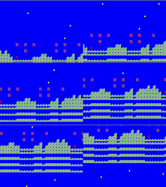
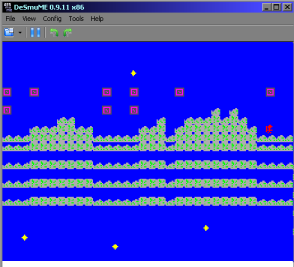
What Is NativeSprite?
| Nativesprite allows us to use platform specific sprite
capabilities, to form 'objects' (grids of sprites which can be
used in the same way on all systems. This allows us to write a multiplatform program, but gain the benefits of the hardware capabilities. Nativesprite splits the job of drawing sprites into three parts. |
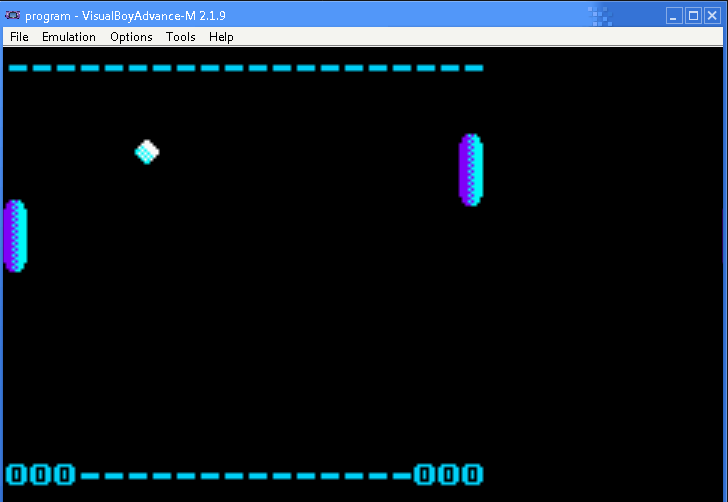 |
| Part 1 is
multiplatform, it is a list of NativeSprite objects with X,Y
co-ordinates (in logical units - Pairs of Pixels) Our game can change the co-ordinates and sprite object pointers to change in-game graphics in a multiplatform way. With ChibiVM, the 16 bit pointer is a 'numbered entry' in the AddressRemapTable. This is to allow 16 bit ChibiVM to address the 32 bit address space of the MIPS |
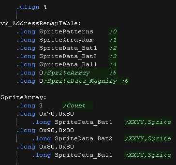 |
| Part 2 is platform
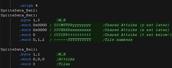
specific, and defines the sprite pattern grid, This defines how the object is made up of hardware sprite patterns. It also offers platform specific functions, like sprite scaling or palettes where available. On systems where no Hardware sprites are available, XOR software sprites are used (made up of 8x8 tiles)... XOR is used because it means we don't need to worry about redrawing the background. On the NDS and GBA we define the top bits for the 'shared attributes' and the tilenumbers for each sprite. Note the X and Y bits will be set automatically depending on the final position of the sprite object Part 3 is also platform specific. This is the bitmap pattern data used to draw the sprite, in the format of the hardware sprites or screen memory. |
  |
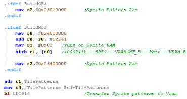
| NativeSpr_Init
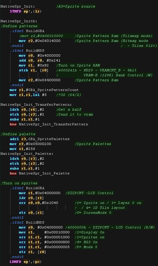
will prepare the system for drawing sprites. On hardware sprite systems, we transfer patterns to VRAM The VRAM destination is different depending on if we're coding for the NDS or GBA On the GBA In Tilemap mode, Sprite patterns are defined by by VRAM addresses 0x06010000+ On the GBA In
Bitmap mode, Sprite patterns are defined by by
VRAM addresses 0x06014000+, Due to the size of the bitmap screen
ram, only tile numbers 512+ are usable
On the NDS Sprite
patterns are defined by by VRAM addresses 0x06400000+
We transfer our pattern data to the correct address for the system. The sprites are 16 color, so we need to define the color palette at addresses 0x05000200+ in the format %-BBBBBGGGGGRRRRR We also need to turn on the sprite layer with port 0x04000000 , the value we send is different on NDS and GBA |
 |
| NativeSpr_DrawArray
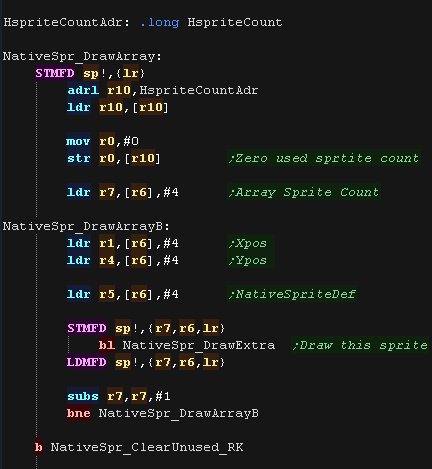
draws the array of sprite objects defined in Part1 The Co-ordinates of the sprite (in pairs of pixels) and the pointer to the sprite object (part 2) There are two versions: NativeSpr_DrawArrayReiKou is used with ChibiVM, and uses the AddressRemapTable to convert a 16 bit pointer to 32 bits. NativeSpr_DrawArray uses a 32 bit pointer... If you're using NativeSprite on it's own, this is the one you would use. We load in the X,Y position the sprite should pbe drawn, and the pointer to the sprite definition. We use NativeSpr_DrawExtra to draw the sprite to the screen. |
 |
| NativeSpr_ClearUnused removes no-longer needed sprites forom the screen, by setting the X,Y pos to 255 (offscreen) | 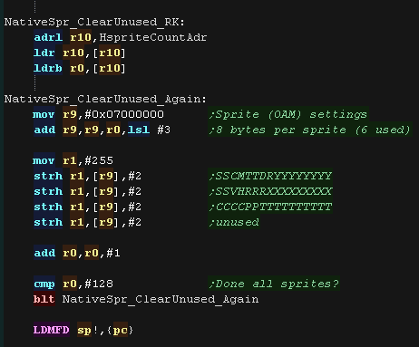 |
| Here is the correct Object definition
for the NDS/GBA systems The Width and Height in patterns is defined in the first two bytes. On the NDS and GBA we define the top bits for the 'shared attributes' and the tilenumbers for each sprite. Note the X and Y bits will be set automatically depending on the final position of the sprite object |
 |
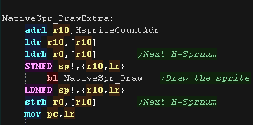
| NativeSpr_DrawExtra
will draw object R5 at position R1,R4 We load the next free hardware sprite number into R0, and run NativeSpr_Draw |
 |
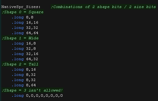
| On the GBA and NDS there are two pairs of two bits that define
the sprite size 2 bits define shape (Square, Wide rectangle, tall rectangle) 2 bits define size (four choices) We have a lookup table to define the pixel sizes of these. |
 |
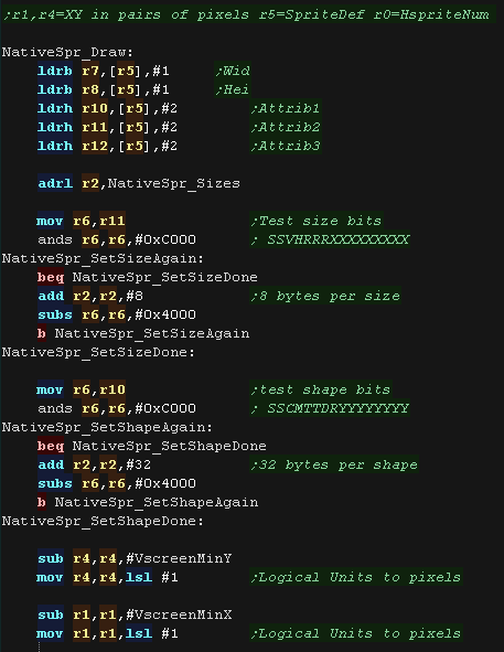
| NativeSpr_Draw
will draw the soprite to position R1,R4 using definition R5 and
hardware sprite R0 First we load in the shared attribute bits and X,Y co=ordinate We calculate the size in pixels of each hardware sprite using the shape and size bits (and our lookup table) The X,Y co-ordinate is in what I call 'logical units' (Pairs of pixels), so we convert the into actual screen pixels! |
 |
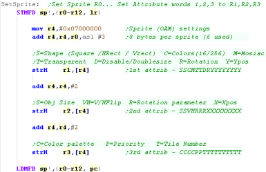
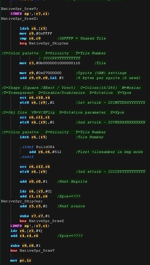
| We define the three 16 bit values for each hardware
sprite, loaded to 0x07000000+ (three 16 bit values, plus a fourth
unused 'spacer) On the GBA the first 512 patterns are not available (as they overlap bitmap memory) We build up the sprite object using multiple hardware sprites, with the 16 bit patterns defined in the SpriteObject After each sprite, we move across the screen by adding the calculated sprite size (from the shape/size bits) We then move down the screen to build up the full sprite. |
 |
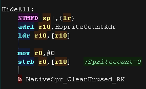
| NativeSpr_HideAll
will remove all the hardware sprites from the screen, and should
be used for things like title screens. It should also be used
before redrawing the background with XOR sprites. It uses the NativeSpr_ClearUnused routine to remove all sprites from the screen |
 |
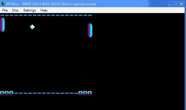
What Is NativeSprite?
| Nativesprite allows us to use platform specific sprite
capabilities, to form 'objects' (grids of sprites which can be
used in the same way on all systems. This allows us to write a multiplatform program, but gain the benefits of the hardware capabilities. Nativesprite splits the job of drawing sprites into three parts. |
 |
| Part 1 is
multiplatform, it is a list of NativeSprite objects with X,Y
co-ordinates (in logical units - Pairs of Pixels) Our game can change the co-ordinates and sprite object pointers to change in-game graphics in a multiplatform way. With ChibiVM, the 16 bit pointer is a 'numbered entry' in the AddressRemapTable. This is to allow 16 bit ChibiVM to address the 32 bit address space of the MIPS |
 |
| Part 2 is platform
specific, and defines the sprite pattern grid, This defines how the object is made up of hardware sprite patterns. It also offers platform specific functions, like sprite scaling or palettes where available. On systems where no Hardware sprites are available, XOR software sprites are used (made up of 8x8 tiles)... XOR is used because it means we don't need to worry about redrawing the background. Part 3 is also platform specific. This is the bitmap pattern data used to draw the sprite, in the format of the hardware sprites or screen memory. |
  |
|
 |
|
| NativeSpr_Init
will prepare the system for drawing sprites. On hardware sprite systems, we transfer patterns to VRAM On the XOR sprite systems we just remember the address we were passed, which contains the bitmap 'tile pattern' data. |
 |
|
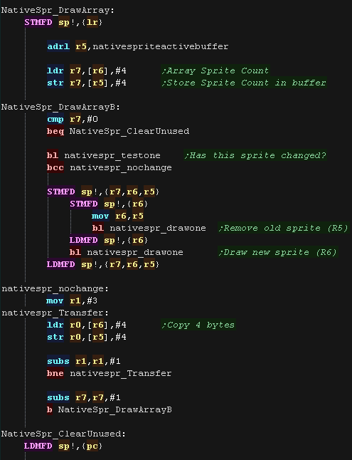
| NativeSpr_DrawArray
draws the array of sprite objects defined in Part1 The Co-ordinates of the sprite (in pairs of pixels) and the pointer to the sprite object (part 2) There are two versions: NativeSpr_DrawArrayReiKou is used with ChibiVM, and uses the AddressRemapTable to convert a 16 bit pointer to 32 bits. NativeSpr_DrawArray uses a 32 bit pointer... If you're using NativeSprite on it's own, this is the one you would use. We need to check if the sprite needs to be drawn, we use nativespr_testone to check if the position or appearance of the sprite has changed We use NativeSpr_DrawOne to draw the sprite to the screen, we also use it to remove any old copy of the sprite - as it's an XOR operation drawing twice to the same position will remove it. |
 |
|
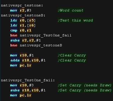
| NativeSpr_TestOne Checks the
'ActiveBuffer' to see if the XOR sprite is already drawn to the
screen at this position If it is it doesn't need redrawing If it has moved or changed, we remove the old sprite (by XOR drawing it in the same position) then draw the new sprite. |
 |
|
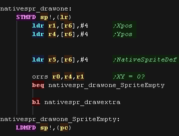
| Nativespr_drawone
will load in the X and Y position of the sprite, and the
SpriteObject definition We use Nativespr_drawextra to draw the SpriteObject at the required position |
 |
|
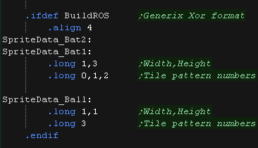
| Here is the correct Object definition
for the XOR systems The Width and Height in patterns is defined in longs the first two . The other longs are the pattern numbers, calculated as offsets to the previously specified source pattern data. |
 |
|
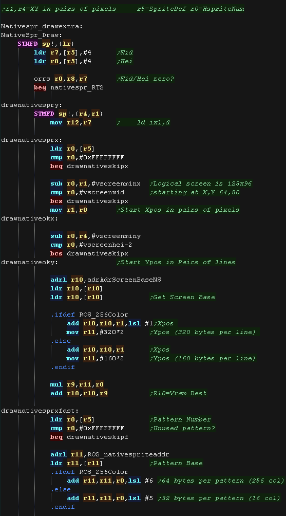
| Nativespr_drawextra
will draw the soprite to position R1,R4 using definition R5 and
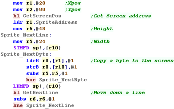
hardware sprite R0 First we load in the shared attribute bits and X,Y co=ordinate The X,Y co-ordinate is in what I call 'logical units' (Pairs of pixels), so we convert the into actual screen pixels! We use these to calculate the vram destination (in R10). In 256 color mode each line is 320 bytes In 16 color mode each line is 160 bytes We also need to calculate the source address for the 8x8 pattern tile (in R11) In 256 color mode each pattern is 64 bytes In 16 color mode each pattern is 32 bytes |
 |
|
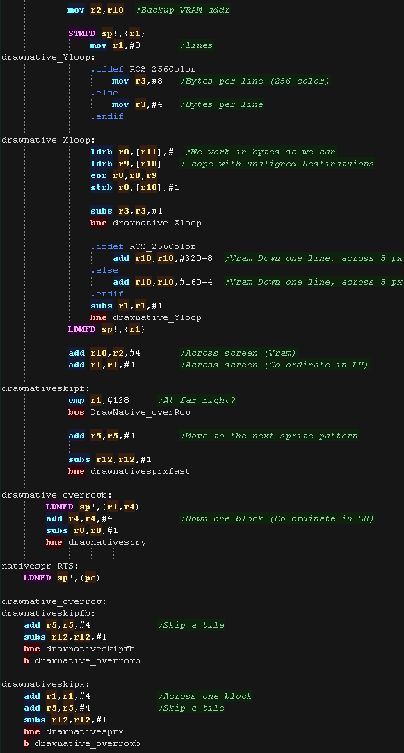
| We transfer the bytes from the source pattern to
the screen. We work in bytes so we don't have alignment issues (we
would have with Half or Words) To move down a line we add 320 bytes (256 color) or 160 bytes (16 color) On the GBA the first 512 patterns are not available (as they overlap bitmap memory) We build up the sprite object using multiple patterns drawnative_overrow copes with times the sprite has gone off the right hand side of the screen drawnativeskipx skips patterns on the left, or patterns which are defined as 'empty' |
 |
|
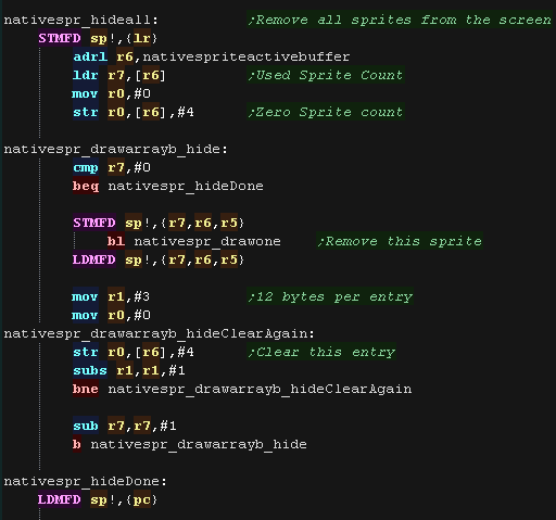
| NativeSpr_HideAll
will remove all the sprites from the screen, by XOR drawing them
in their original position We then clear the data in the buffer. |
 |
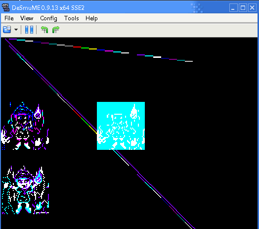
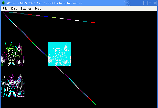
What Is Multiplatform Bitmap?
| Multiplaform bitmap allows us to draw graphics in a common way,
whatever the capabilities of the system! It's intended for low speed drawing or real-time calculated drawing, like drawing title screens, or graphs, or even making a sprite editor or other graphics package! There are 4 functions provided: mpbitmap_setpixel - Set a pixel to a color (0-15) mpbitmap_getpixel - Reads a pixel from the screen mpbitmap_settile - Set an 8x8 pixel tile block (in bitplane format, 1-4 bitplanes) mpbitmap_gettile - Get an 8x8 pixel tile block from the screen (in bitplane format, 1-4 bitplanes) |
 |
Pixel Commands
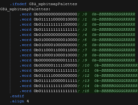
| Multiplatform bitmap is designed to work with a 16
color palette, but the NDS and GBA screens are 16bpp color. To allow Multiplatform bitmap to work, we define a 'palette' which will be used to convert the 0-15 palette number to a RGB Screen format color |
 |
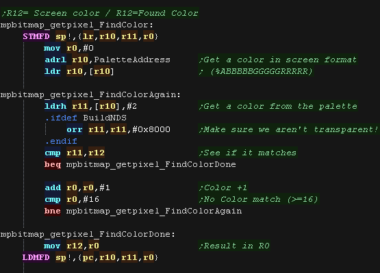
| mpbitmap_getpixel_FindColor will
scan the palette to find a matching color number (0-15) from a
source screen format 16 bit half. We scan up to 16 entries, and return the matching color. |
 |
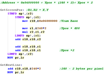
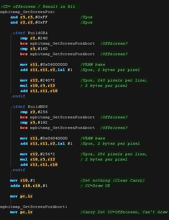
| mpbitmap_GetScreenPos
calculates the VRAM destination On the NDS the screen is 256 pixels wide, each pixel is 2 bytes, and VRAM starts from 0x06040000, so our formula is VRAM = 0x06040000 + (Ypos * 256*2) + (Xpos*2) On the GBA the screen is 240 pixels wide, each pixel is 2 bytes, and VRAM starts from 0x06000000, so our formula is VRAM = 0x06000000 + (Ypos * 240*2) + (Xpos*2) If we're asked for a pixel which is 'offscreen' we set the carry flag, to warn the calling routine the draw or read is impossible |
 |
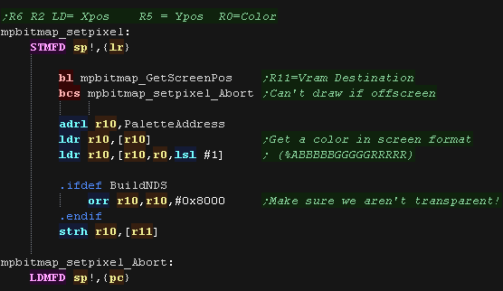
| mpbitmap_setpixel draws a pixel to
the screen The color to set is specified in S0 The Y position in pixels is specified in S5 The X position is specified in S2 We use GetScreenPos to calculate the VRAM destination, and lookup the color in the palette. We write the color to the screen. on the NDS we ensure the top bit is set (Alpha) - otherwise the pixel will be transparent! |
 |
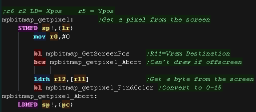
| The mpbitmap_getpixel
function gets a pixel back from the screen We use mpbitmap_GetScreenPos to calculate the source VRAM address, |
 |
Tile Commands
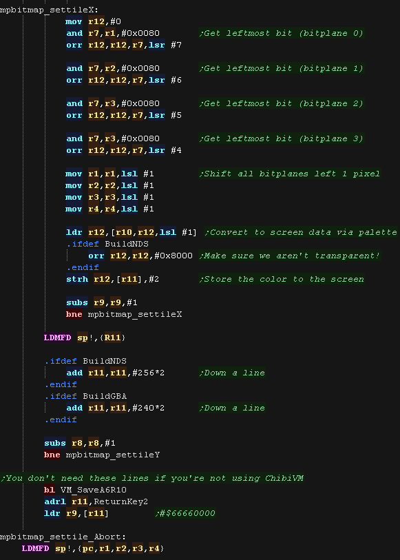
| The 'mpbitmap_settile'
command will take an 8x8 block of data in bitplane format, and draw
it to the screen. Up to 4 bitplanes are supported, meaning 16 colors, 32 bytes for the full tile. We start by calculating the VRAM destination using GetScreenPos Next we load in the bitplanes we've been provided with from r6, The source data may be less than 4 bitpanes (specified by r0) , so we load any others from the default 'MpBitmap_TileTints' |
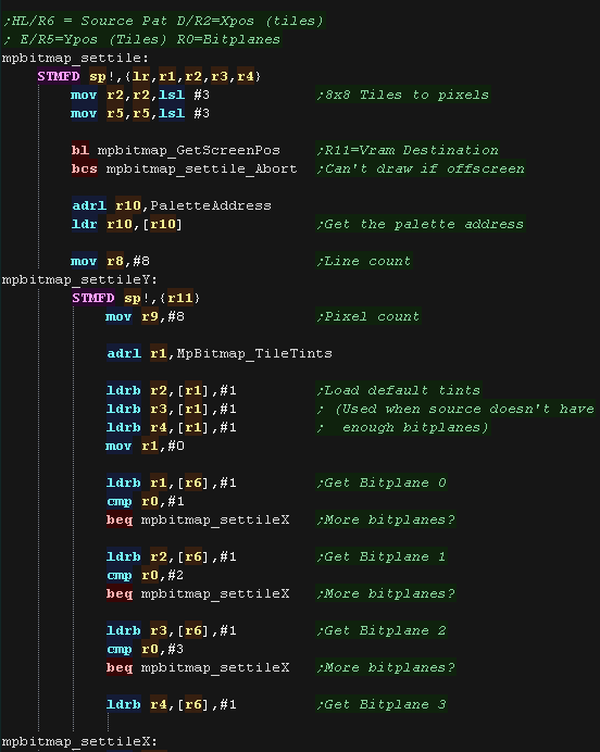 |
| To calculate the color number we take the most
significant bit from each bitplane byte. We use this as a lookup in our palette, giving us a 16 bit screen-format color, and store it to the screen We do this 8 times per line To move down a line we add 256*2 or 240*2 to move down a line, depending on the screen. |
 |
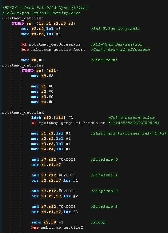
| mpbitmap_gettile will
read pixel data back from the screen, returning 1-4 bitplanes as
required. We calculate the source VRAM address using mpbitmap_GetScreenPos We read data from the screen, loading in a half, nad converting it using mpbitmap_getpixel_FindColor. We shift the 4 bits from the color number into the 4 bitplane 'buldup values in r1-r4. We do this 8 times for the 8 pixels from the screen, completing the 4 bitplane values. |
 |
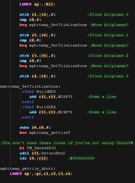
| We store the data back to address r6, writing back as
many bitplanes as we were asked to specified by r0 |
 |
What Is Multiplatform Bitmap?
| Multiplaform bitmap allows us to draw graphics in a common way,
whatever the capabilities of the system! It's intended for low speed drawing or real-time calculated drawing, like drawing title screens, or graphs, or even making a sprite editor or other graphics package! There are 4 functions provided: mpbitmap_setpixel - Set a pixel to a color (0-15) mpbitmap_getpixel - Reads a pixel from the screen mpbitmap_settile - Set an 8x8 pixel tile block (in bitplane format, 1-4 bitplanes) mpbitmap_gettile - Get an 8x8 pixel tile block from the screen (in bitplane format, 1-4 bitplanes) |
 |
Pixel Commands
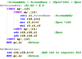
| mpbitmap_GetScreenPos
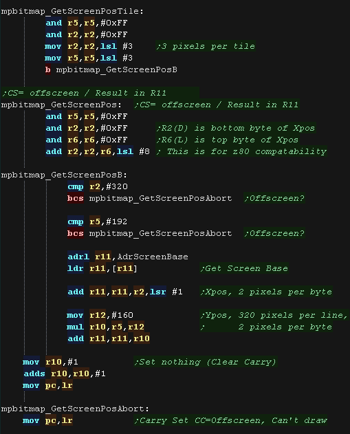
calculates the VRAM destination The Low byte of the X position is specified in R2 The High byte of the X position is specified in R6 (The X position is split into two registers to maintain functional compatibility with the Z80 Version!) The screen is 320 pixels wide, but each byte contains 2 pixels, therefore our VRAM formula is: VRAM = ScreenBase + (Ypos * 160) + (Xpos/2) If we're asked for a pixel which is 'offscreen' we set the carry flag, to warn the calling routine the draw or read is impossible mpbitmap_GetScreenPosTile is the alternative version, which uses an X,Y co-ordinate in tile blocks, rather than pixels |
 |
| mpbitmap_setpixel
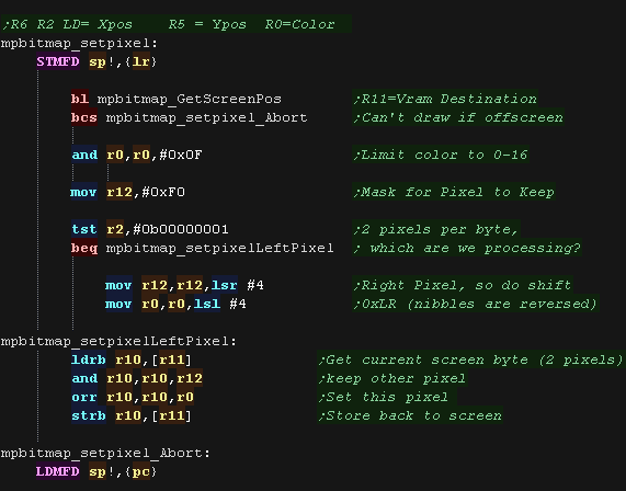
draws a pixel to the screen The color to set is specified in S0 The Y position in pixels is specified in S5 The X position is specified in S2/S6 We use GetScreenPos to calculate the VRAM destination. Each byte contains two pixels, so we need to keep one, and change the other... We put a mask in R12, and shift the mask depending on if the pixel we've been asked to change is the left one, or the right one. |
 |
| The mpbitmap_getpixel
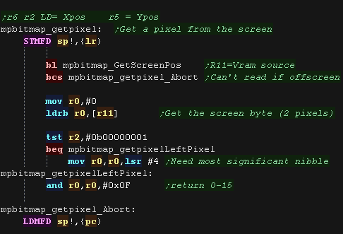
function gets a pixel back from the screen Once again We use mpbitmap_GetScreenPos to calculate the source VRAM address, We read in the byte from the screen, and mask to keep the pixel we want. |
 |
Tile Commands
| The 'mpbitmap_settile'
command will take an 8x8 block of data in bitplane format, and draw
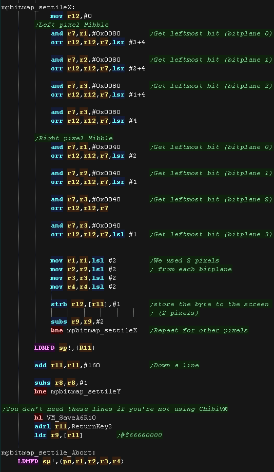
it to the screen. Up to 4 bitplanes are supported, meaning 16 colors, 32 bytes for the full tile. We start by calculating the VRAM destination using GetScreenPos Next we load in the bitplanes we've been provided with from r6, The source data may be less than 4 bitpanes (specified by r0) , so we load any others from the default 'MpBitmap_TileTints' |
 |
| To calculate the color number we take the most
significant bit from each bitplane byte. We use two bits from each bitplane of our source data to build up a 2 pixel byte. We write this byte to the screen, and repeat 4 times for the line of the tile To move down a line we add 160 bytes, as each line is 320 pixels |
 |
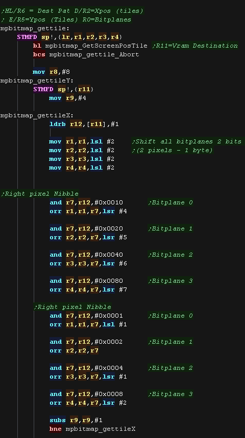
| mpbitmap_gettile will
read pixel data back from the screen, returning 1-4 bitplanes as
required. We calculate the source VRAM address using mpbitmap_GetScreenPos We read data from the screen, loading in a byte which contains two pixels. We get the 4 bits of the color (0-15) for the left and right pixel into the bitplane data store in R1-R4. We repeat this 4 times. to read 8 bytes and fill our bitplanes |
 |
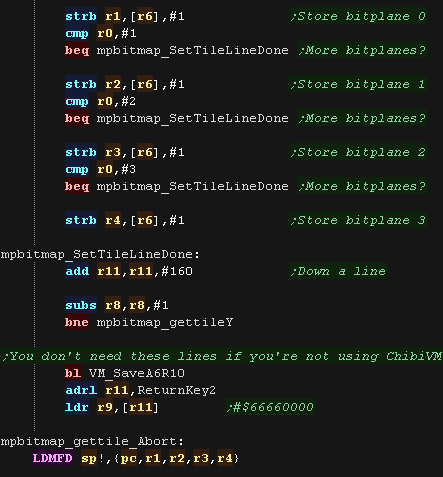
| We store the data back to address r6, writing back as
many bitplanes as we were asked to specified by r0 |
 |
| View Options |
| Default Dark |
| Simple (Hide this menu) |
| Print Mode (white background) |
| Top Menu |
| ***Main Menu*** |
| Youtube channel |
| Patreon |
| Introduction to Assembly (Basics for absolute beginners) |
| Amazon Affiliate Link |
| AkuSprite Editor |
| ChibiTracker |
| Dec/Bin/Hex/Oct/Ascii Table |
| Alt Tech |
| Archive.org |
| Bitchute |
| Odysee |
| Rumble |
| DailyMotion |
| Please note: I wlll upload more content to these alt platforms based on the views they bring in |
| 68000 Content |
| ***68000 Tutorial List*** |
| Learn 68000 Assembly |
| Hello World Series |
| Platform Specific Series |
| Simple Samples |
| Grime 68000 |
| 68000 Downloads |
| 68000 Cheatsheet |
| Sources.7z |
| DevTools kit |
| 68000 Platforms |
| Amiga 500 |
| Atari ST |
| Neo Geo |
| Sega Genesis / Mega Drive |
| Sinclair QL |
| X68000 (Sharp x68k) |
| 8086 Content |
| Learn 8086 Assembly |
| Platform Specific Series |
| Hello World Series |
| Simple Samples |
| 8086 Downloads |
| 8086 Cheatsheet |
| Sources.7z |
| DevTools kit |
| 8086 Platforms |
| Wonderswan |
| MsDos |
| ARM Content |
| Learn ARM Assembly |
| Learn ARM Thumb Assembly |
| Platform Specific Series |
| Hello World |
| Simple Samples |
| ARM Downloads |
| ARM Cheatsheet |
| Sources.7z |
| DevTools kit |
| ARM Platforms |
| Gameboy Advance |
| Nintendo DS |
| Risc Os |
| Risc-V Content |
| Learn Risc-V Assembly |
| Risc-V Downloads |
| Risc-V Cheatsheet |
| Sources.7z |
| DevTools kit |
| MIPS Content |
| Learn Risc-V Assembly |
| Platform Specific Series |
| Hello World |
| Simple Samples |
| MIPS Downloads |
| MIPS Cheatsheet |
| Sources.7z |
| DevTools kit |
| MIPS Platforms |
| Playstation |
| N64 |
| PDP-11 Content |
| Learn PDP-11 Assembly |
| Platform Specific Series |
| Simple Samples |
| PDP-11 Downloads |
| PDP-11 Cheatsheet |
| Sources.7z |
| DevTools kit |
| PDP-11 Platforms |
| PDP-11 |
| UKNC |
| TMS9900 Content |
| Learn TMS9900 Assembly |
| Platform Specific Series |
| Hello World |
| TMS9900 Downloads |
| TMS9900 Cheatsheet |
| Sources.7z |
| DevTools kit |
| TMS9900 Platforms |
| Ti 99 |
| 6809 Content |
| Learn 6809 Assembly |
| Learn 6309 Assembly |
| Platform Specific Series |
| Hello World Series |
| Simple Samples |
| 6809 Downloads |
| 6809/6309 Cheatsheet |
| Sources.7z |
| DevTools kit |
| 6809 Platforms |
| Dragon 32/Tandy Coco |
| Fujitsu FM7 |
| TRS-80 Coco 3 |
| Vectrex |
| 65816 Content |
| Learn 65816 Assembly |
| Hello World |
| Simple Samples |
| 65816 Downloads |
| 65816 Cheatsheet |
| Sources.7z |
| DevTools kit |
| 65816 Platforms |
| SNES |
| eZ80 Content |
| Learn eZ80 Assembly |
| Platform Specific Series |
| eZ80 Downloads |
| eZ80 Cheatsheet |
| Sources.7z |
| DevTools kit |
| eZ80 Platforms |
| Ti84 PCE |
| IBM370 Content |
| Learn IBM370 Assembly |
| Simple Samples |
| IBM370 Downloads |
| IBM370 Cheatsheet |
| Sources.7z |
| DevTools kit |
| Super-H Content |
| Learn SH2 Assembly |
| Hello World Series |
| Simple Samples |
| SH2 Downloads |
| SH2 Cheatsheet |
| Sources.7z |
| DevTools kit |
| SH2 Platforms |
| 32x |
| Saturn |
| PowerPC Content |
| Learn PowerPC Assembly |
| Hello World Series |
| Simple Samples |
| PowerPC Downloads |
| PowerPC Cheatsheet |
| Sources.7z |
| DevTools kit |
| PowerPC Platforms |
| Gamecube |
| Work in Progress |
| ChibiAndroids |
| Misc bits |
| Ruby programming |
Buy my Assembly programming book
on Amazon in Print or Kindle!


Available worldwide!
Search 'ChibiAkumas' on
your local Amazon website!
Click here for more info!


Buy my Assembly programming book
on Amazon in Print or Kindle!


Available worldwide!
Search 'ChibiAkumas' on
your local Amazon website!
Click here for more info!


Buy my Assembly programming book
on Amazon in Print or Kindle!


Available worldwide!
Search 'ChibiAkumas' on
your local Amazon website!
Click here for more info!


Buy my Assembly programming book
on Amazon in Print or Kindle!


Available worldwide!
Search 'ChibiAkumas' on
your local Amazon website!
Click here for more info!


Buy my Assembly programming book
on Amazon in Print or Kindle!


Available worldwide!
Search 'ChibiAkumas' on
your local Amazon website!
Click here for more info!


Buy my Assembly programming book
on Amazon in Print or Kindle!


Available worldwide!
Search 'ChibiAkumas' on
your local Amazon website!
Click here for more info!


